
Device and method for storing thermal energy

a technology of thermal energy and storage device, which is applied in the direction of storage heaters, domestic heating details, space heating and ventilation details, etc., can solve the problems of difficult management of lack of uniform consumption, difficult situation, and uniform energy demand emanating from climatic apparatuses, and achieve high thermal diffusivity, reduce the division of pcm, and high degree of porosity

Active Publication Date: 2017-08-03
MULLER & CIE
View PDF6 Cites 26 Cited by
  • Summary
  • Abstract
  • Description
  • Claims
  • Application Information

AI Technical Summary

Benefits of technology

The patent describes a support system that helps to keep a phase change material (PCM) at a uniform temperature, without causing the PCM to become too cool or too hot. This support system also helps to store energy when it’s being consumed, and to reduce or stop energy consumption when it’s not being used.

Problems solved by technology

The energy demand emanating from climatic apparatuses is not uniform throughout the day, week or year.
This lack of uniformity of the consumption is particularly tricky to manage when the energy consumption is electric and when it cannot be stored as such.
The situation is more particularly tricky when the energy production uses uncontrolled intermittent production means, such as wind or solar means.
Both the peak periods and off-peak periods pose a problem.
However, this thermodynamic principle encounters practical difficulties.
A first difficulty is linked to obtaining a uniform temperature in the body that is the subject of the phase transition.
Indeed, the phase change materials (PCM) are not by themselves good heat conductors.
Thus, when the heat transfer fluid intended to extract the latent heat therefrom, for example air, sweeps over the surface of the block, the thermal resistance that accumulates between the external exchange surface and the state change front rapidly becomes predominant and limits the thermal power.
Besides the cost of these materials, this method from the prior art also has implementation drawbacks.
Thus, the solution from the prior art that consists in separating, by encapsulation, the PCM into small amounts is disadvantageous from the point of view of supercooling.

Method used


Image

  • Device and method for storing thermal energy
  • Device and method for storing thermal energy
  • Device and method for storing thermal energy

Examples


Embodiment Construction

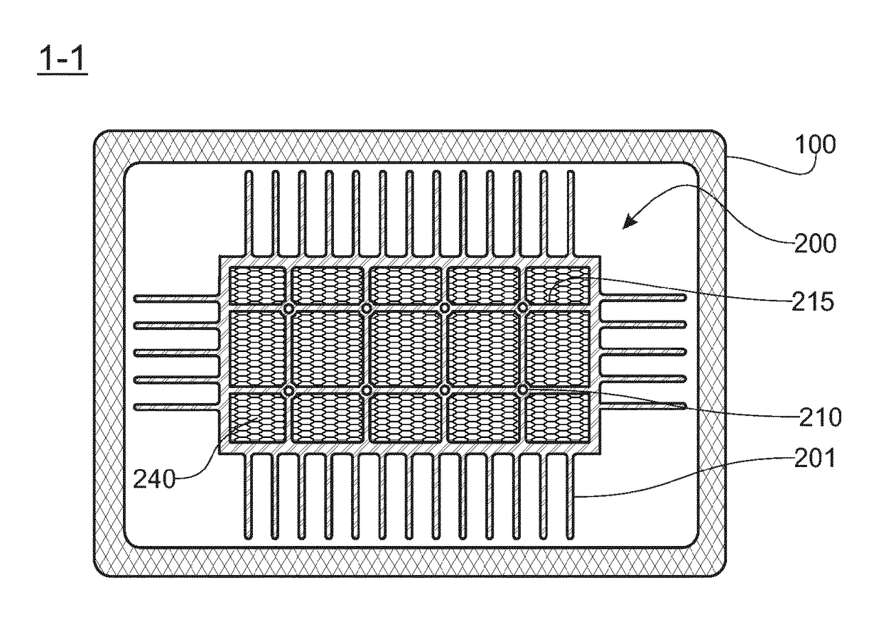
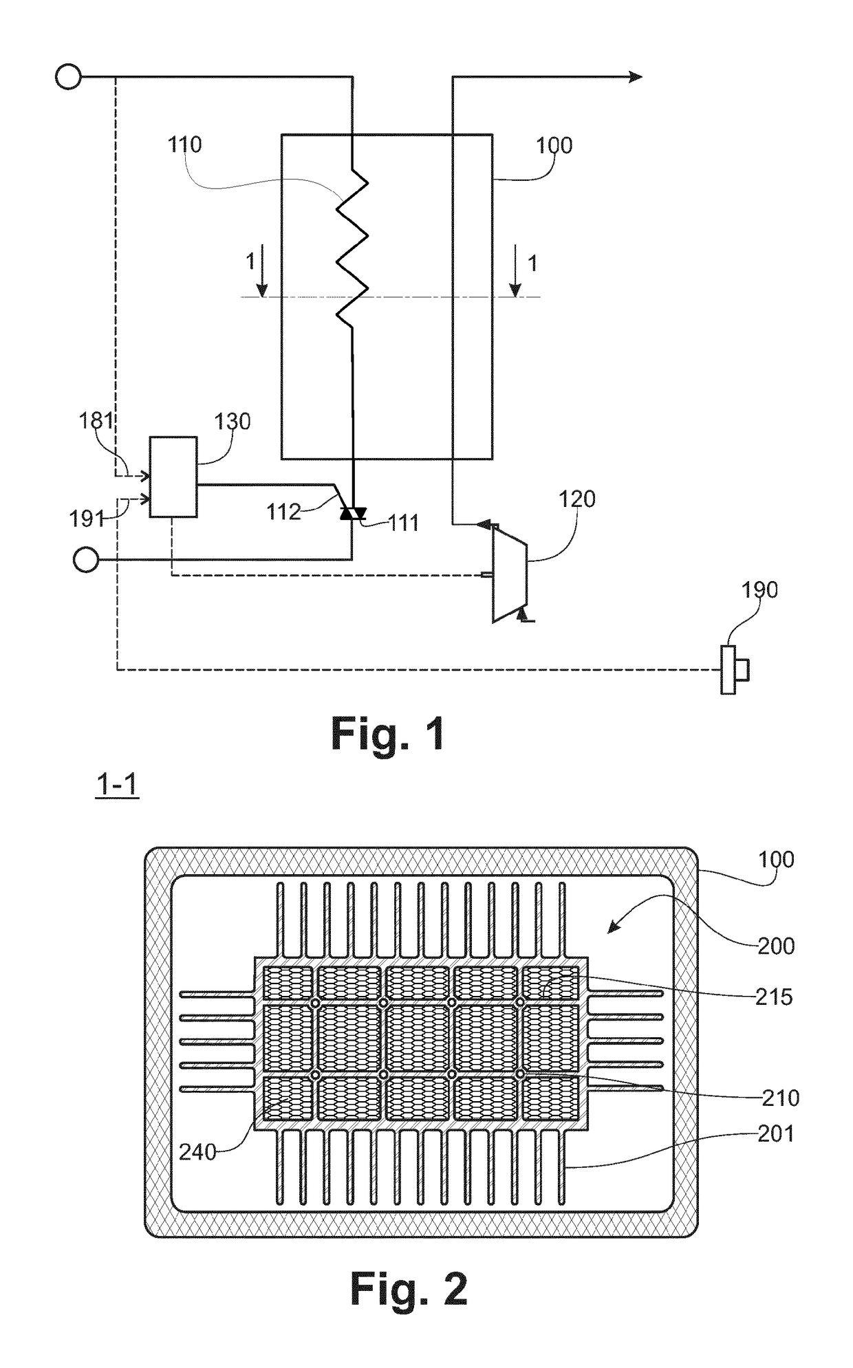
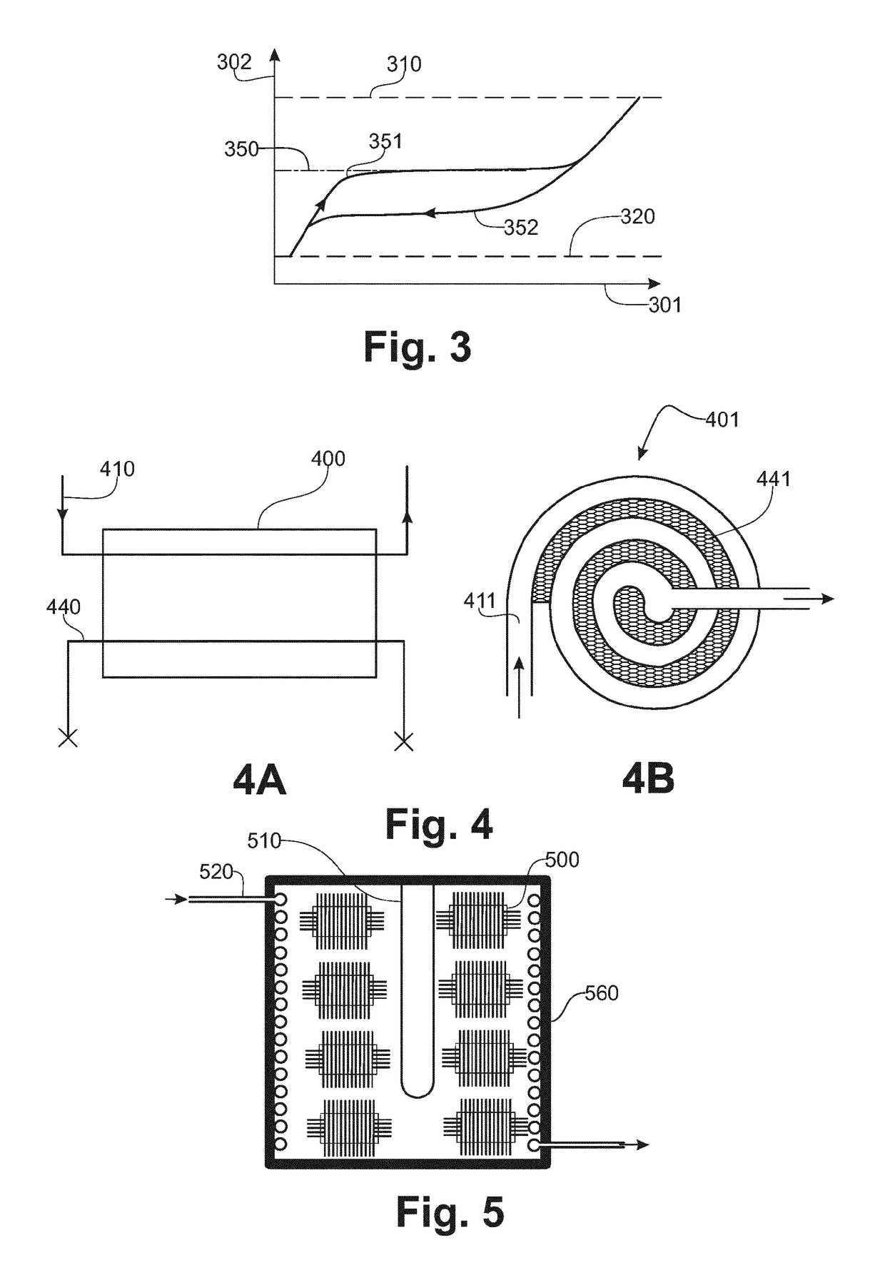
[0062]FIG. 1, according to one schematic implementation and embodiment example of the device that is the subject of the invention, this device comprises a source (110), such as an electric resistance heater, which resistance heater is connected to the electrical network and the operation of which is, for example, controlled by means of a TRIAC (111), the trigger gate (112) of which is controlled by a control device (130). Said control device (130) comprises, according to one exemplary embodiment, computational and memory means, an output interface and an input interface. The trigger gate (112) of the TRIAC (111) is connected to the output interface. According to this exemplary embodiment, the resistance heater (110), when it is supplied with electrical current, heats an energy storage core included in a thermally insulating chamber (100). A turbine (120) makes it possible to blow air into said chamber, so that the air is heated in contact with the energy storage core before being se...


PUM


Abstract

A device to store energy includes a phase change material (PCM), with a phase change temperature Tc, contained in a sealed container and constituting a storage core. A source to exchange heat with the PCM, at a temperature TA, to cause a phase change of the PCM. A recuperator to exchange heat with the PCM, at a temperature TB, to cause a phase change of the PCM in the opposite direction to the phase change produced by the source. A controller to control the heat flows between the PCM, the source and the recuperator. An apertured support in contact with the PCM in the sealed container and in thermal contact with the source and the recuperator.

Description

RELATED APPLICATIONS[0001]This application is a §371 application from PCT / EP2015 / 066950 filed Jul. 23, 2015, which claims priority from French Patent Application No. 14 57129 filed Jul. 23, 2014 and French Patent Application No. 15 51741 filed Mar. 02, 2015, each of which is incorporated herein by reference in its entirety.FIELD OF THE INVENTION[0002]The invention relates to a device and a method for storing thermal energy. The invention is more particularly, but not exclusively, intended for an climatic apparatus or for a facility that uses apparatuses for controlling the climatic environment in a premises. The terms “climatic apparatus” denote any device for heating, air conditioning, mechanical ventilation or production of water at controlled temperature.BACKGROUND OF THE INVENTION[0003]Such climatic apparatuses consume energy, generally of electrical origin, which electrical energy is used directly to produce heat, for example by the passage thereof through an electric resistanc...

Claims


Application Information

Patent Timeline
IPC IPC(8): F28D20/02C09K5/06F24H7/02F24F5/00F24H9/20
CPCF28D20/023F24F5/0021C09K5/063F24H7/0216F24H9/2078F24H7/0416F24D2220/10F28F3/048F28F21/084C09K5/06F24F5/0096F28D20/021Y02E60/14F24H15/144F24H15/45F24H15/407F24H15/265F24H15/20F24H15/254F24H15/31F24H15/37
Inventor LONGIS, ALEXANDREPOURRAT, FRAN OISMORARD, JEAN-LOUIS
Owner MULLER & CIE
Learn More