
Substrate cleaning device, substrate processing apparatus, substrate cleaning method and substrate processing method

Active Publication Date: 2017-08-03
SCREEN HLDG CO LTD
View PDF2 Cites 5 Cited by
  • Summary
  • Abstract
  • Description
  • Claims
  • Application Information

AI Technical Summary

Benefits of technology

The invention provides a substrate cleaning device and a substrate processing apparatus that can remove foreign matter adhering to the back surface of a substrate. The substrate cleaning method and the substrate processing method ensure that the substrate is prevented from bending, which allows for a uniform load to be applied to the back surface of the substrate for sufficient cleaning. The invention helps to reliably remove foreign matter firmly adhering to the back surface of the substrate, the coating film that is formed when the coating liquid flows to the back surface of the substrate, and foreign matter mixed with the coating film.

Problems solved by technology

However, in the cleaning drying processing unit described in JP 2009-123800 A, it is difficult to remove foreign matter firmly adhering to the back surface of the substrate, a coating film that is formed when the coating liquid flows to the back surface of the substrate, foreign matter mixed with the coating film and the like.

Method used


Image

  • Substrate cleaning device, substrate processing apparatus, substrate cleaning method and substrate processing method
  • Substrate cleaning device, substrate processing apparatus, substrate cleaning method and substrate processing method
  • Substrate cleaning device, substrate processing apparatus, substrate cleaning method and substrate processing method

Examples


first embodiment

[0062](1) Substrate Processing Apparatus

[0063]A substrate cleaning device and the substrate processing apparatus according to the first embodiment of the present invention will be described below with reference to drawings. In the following description, a substrate refers to a semiconductor substrate, a substrate for a liquid crystal display device, a substrate for a plasma display, a substrate for an optical disc, a substrate for a magnetic disc, a substrate for a magneto-optical disc, a substrate for a photomask or the like. Further, the substrate used in the present embodiment has an at least partially circular outer peripheral end. For example, the outer peripheral end except for a notch for positioning is circular.

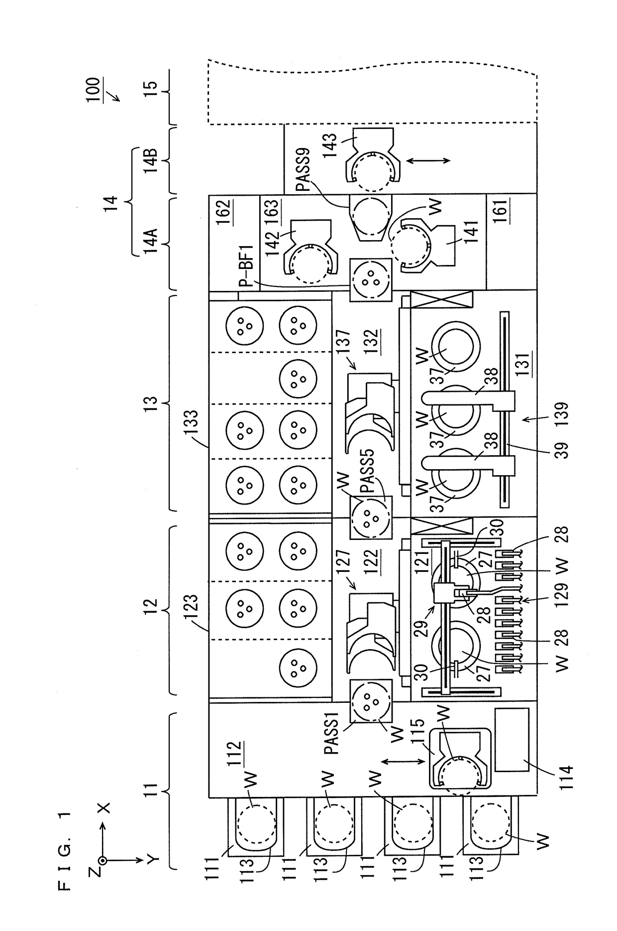
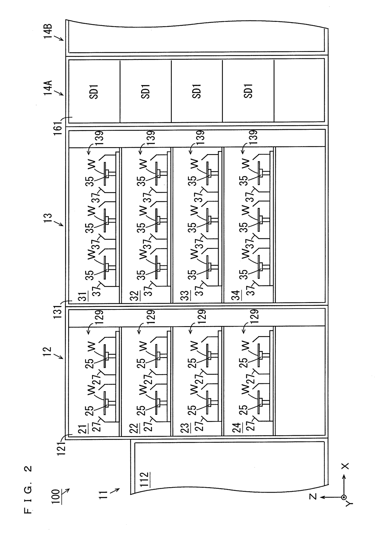
[0064]FIG. 1 is a schematic plan view of the substrate processing apparatus according to the first embodiment of the present invention. FIG. 1 and the subsequent drawings are accompanied by arrows that indicate X, Y, and Z directions orthogonal to one another for the ...

second embodiment

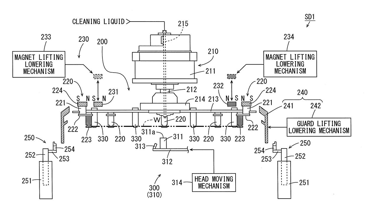
[0181]As for a substrate cleaning device and a substrate processing apparatus according to the second embodiment, differences from the substrate cleaning device and the substrate processing apparatus according to the first embodiment will be described. FIG. 19 is a partial longitudinal cross sectional view showing a configuration of a cleaning drying processing unit SD1 in the second embodiment of the present invention. FIG. 20 is an enlarged side view of a cleaning head 311 in the cleaning drying processing unit SD1 of FIG. 19. As shown in FIG. 19, in the present embodiment, a cleaning unit 300 does not include a plurality of auxiliary pins 330.

[0182]Further, in the present embodiment, the shape of a holder 223 of each chuck pin 220 is different from the shape of the holder 223 of each chuck pin 220 of FIG. 4. In the example of FIG. 19, a lower portion of the holder 223 has a truncated cone-shape, and an upper portion of the holder 223 is columnar. A diameter in a horizontal plane ...


PUM


Abstract

An outer peripheral end of the substrate is held with a plurality of chuck pins provided at a spin plate abutting against a plurality of portions of the outer peripheral end of the substrate, and the spin plate is rotated about a rotation axis. A cleaning head is moved by a head moving mechanism while being pressed against a back surface of the substrate held by the plurality of chuck pins by the head moving mechanism, and foreign matter on the back surface of the substrate is removed by polishing with the cleaning head. A reaction force against a load applied to the back surface of the substrate by the cleaning head is generated in the substrate by auxiliary pins. Alternatively, the back surface of the substrate, which has been cleaned or is being cleaned by the cleaning head, is further cleaned by a cleaning brush.

Description

BACKGROUND OF THE INVENTION[0001]Field of the Invention[0002]The present invention relates to a substrate cleaning device and a substrate processing apparatus that clean substrates and a substrate cleaning method and a substrate processing method for cleaning substrates.[0003]Description of Related Art[0004]In a lithography process in manufacturing of a semiconductor device and the like, a coating film is formed by supply of a coating liquid such as a resist liquid to an upper surface of a substrate. The coating film is exposed to exposure light and then developed, so that a predetermined pattern is formed on the coating film. Cleaning processing is performed on the substrate before the exposure of the coating film (see JP 2009-123800 A, for example).[0005]In JP 2009-123800 A, a substrate processing apparatus having a cleaning drying processing unit is described. In the cleaning drying processing unit, the substrate is rotated while being horizontally held by a spin chuck. In this s...

Claims


Application Information

Patent Timeline
IPC IPC(8): H01L21/02H01L21/687B08B7/04B08B1/02B08B3/02H01L21/67B08B1/00
CPCH01L21/0209H01L21/67051H01L21/68764B08B7/04B08B1/002B08B1/02B08B3/022H01L21/67046H01L21/02057H01L21/68792B08B1/00B08B11/02H01L21/68728H01L21/68742B08B1/12B08B1/20
Inventor NISHIYAMA, KOJI
Owner SCREEN HLDG CO LTD
Learn More