Hybrid electric power drive system for a rotorcraft

a hybrid electric drive and rotorcraft technology, applied in the direction of engine-driven generators, propulsion by batteries/cells, transportation and packaging, etc., can solve the problems of increasing oei power ratings or providing additional supplemental power, difficult, expensive, etc., and achieve the effect of improving one or more desired performance parameters

Active Publication Date: 2017-08-10
SIKORSKY AIRCRAFT CORP
View PDF19 Cites 66 Cited by
  • Summary
  • Abstract
  • Description
  • Claims
  • Application Information

AI Technical Summary

Benefits of technology

[0006]Technical function of the one or more claims described above provides supplemental power to a helicopter's drivetrain through a hybrid electric drive system that receives power from at least one of a rechargeable energy source or a non-rechargeable energy source while improving one or more desired performance parameters, such as payload, fuel economy, system cost, etc.

Problems solved by technology

However, increases to OEI power ratings or providing additional supplemental power is difficult, expensive, and may not be possible over the entire envelope without significant engine redesign.

Method used


Image

  • Hybrid electric power drive system for a rotorcraft
  • Hybrid electric power drive system for a rotorcraft
  • Hybrid electric power drive system for a rotorcraft

Examples


Embodiment Construction

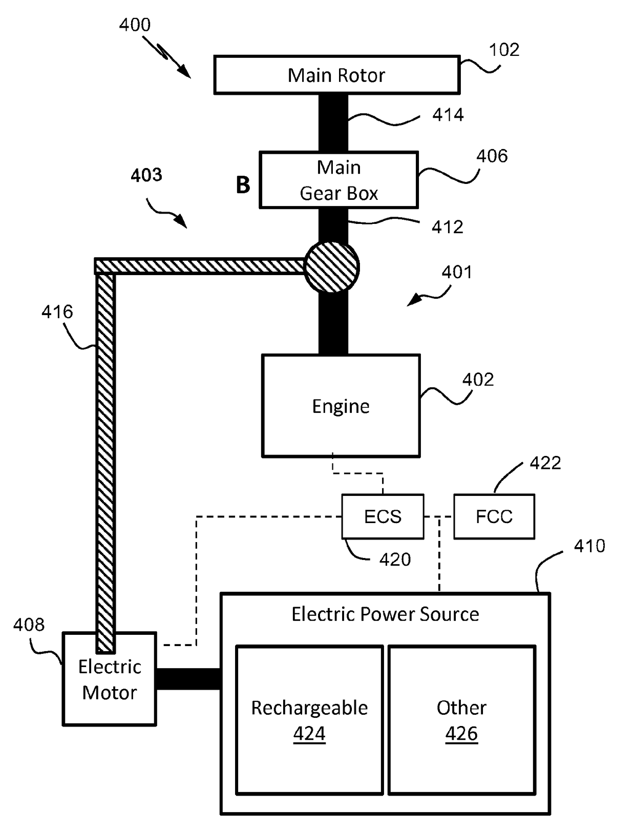
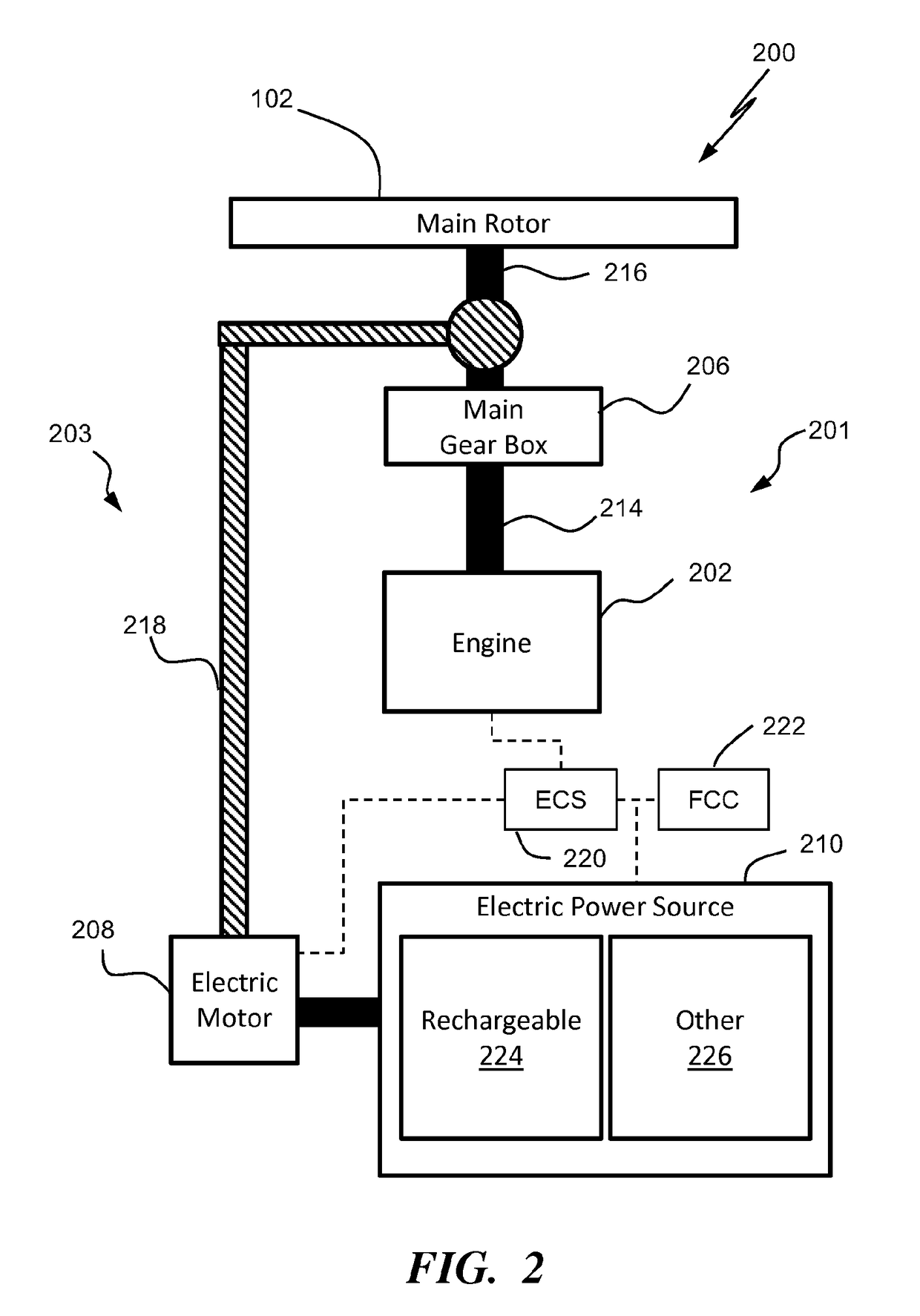
[0013]A hybrid electric drive system that can provide power to a rotary wing aircraft's rotor system which improves one or more performance parameters, such as payload, fuel economy, system cost, etc.

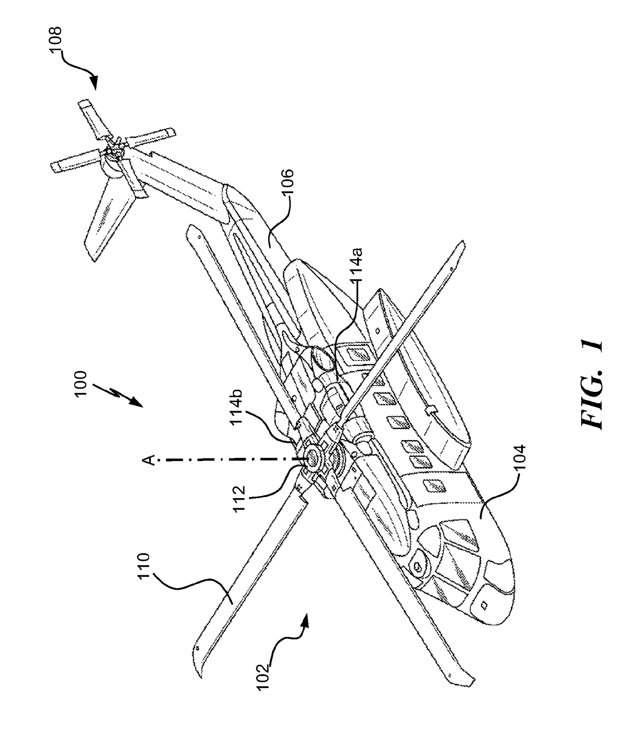
[0014]FIG. 1 schematically illustrates an aircraft 100 (e.g., helicopter or rotorcraft), which includes a hybrid electric power drive system (shown in FIGS. 2-4) that provides supplemental aircraft power in accordance with embodiments of the invention. The hybrid electric power drive system includes a main drive system in serial or in parallel with an auxiliary drive system. The auxiliary drive system provides, in embodiments, a limited duration boost of power to the rotors of rotorcraft 100 in order to achieve a safe-flight condition as well as longer duration normal operation power to the rotors of the aircraft 100 during increased demand of a single-engine and multi-engine rotorcraft, e.g., the aircraft 100. The hybrid electric power drive system is described below in relation to FIG...


PUM


Abstract

A hybrid power drive system for an aircraft that comprises a rotor and a first power drive sub-system. The first power drive sub-system includes at least one engine in connection with the rotor and provides a first power to the rotor. The hybrid power drive system also includes a second power drive sub-system connected in parallel to the first power drive sub-system, which supplements with a second power the first power delivered to the rotor during operation of the aircraft. In addition, an electric power source provides a third power to the second power drive sub-system.

Description

FIELD OF THE INVENTION[0001]The subject matter disclosed herein relates generally to the field of propulsion systems, and to a rotorcraft with a parallel hybrid electric drive system that receives energy from one of two classes of electric power sources.BACKGROUND OF THE INVENTION[0002]Rotary wing aircraft utilize propulsion systems to power aircraft flight. These propulsion systems convert stored energy into mechanical work to drive one or more rotor systems for flight. Energy (typically stored in chemical form as fuel) is supplied to an energy conversion device (typically a plurality of internal combustion engines such as a turbine engine, spark ignition engine, or compression ignition engine), which converts the energy into mechanical work. A drive system transmits mechanical work through a plurality of transmission mechanisms (e.g., main rotor gearbox(es), a tail rotor gearbox, intermediate gearbox(es), drive shafts, drive couplings, etc.) to drive the rotary wing aircraft's thr...

Claims


Application Information

Patent Timeline
Patent Type & Authority Applications(United States)
IPC IPC(8): B60L11/14B60L11/16B60L11/18B64C27/12B64D27/24B60L50/16B60L50/30
CPCB60L11/14B64C27/12B64D27/24B60L2200/10B60L11/16B64D2027/026B60L11/18B64D27/26B60L50/50B60L50/16B60L50/30Y02T10/70Y02T50/60
Inventor WALTNER, PETER JAMES
Owner SIKORSKY AIRCRAFT CORP
Why Eureka
Try Eureka