Protected capacitor system and method

Inactive Publication Date: 2017-08-10
MJG INNOVATIONS LLC
View PDF0 Cites 24 Cited by
  • Summary
  • Abstract
  • Description
  • Claims
  • Application Information

AI Technical Summary

Benefits of technology

[0030]The parallel shunting TVS/SDR pairs may be integrated into a printed circuit board (PCB) assembly that is externally attached to the capacitor structure or encapsulated in an enclosure incorporating the ca

Problems solved by technology

While the RUN capacitor (0119, 0219) typically has a working voltage of 370-440 VAC in operating environments where the AC power input (0101, 0201) is 240-330 VAC, this overvoltage margin has proven to be insufficient to prevent transient overvoltaaes from occurring across the RUN capacitor (0119, 0219) which generate partial discharges within the capacitor dielectric and eventually cause the capacitor to lose effective capacitance, incur excessive internal series resistance, and/or fail due to a puncture shorting of the capacitor plates through the insulating dielectric of the capacitor.
Field reliability studies have shown that the RUN capacitor (0119, 0219) has a high probability of failure in any electric motor (0110, 0210) system, and this failure probability is especially high in harsh environment applications that are normally associated with HVAC air conditioner/heat pump compressor motors and the like.
The environmental temperature extremes in which the RUN capacitor (0119) operates and external system mechanical vibration can cause intern

Method used


Image

  • Protected capacitor system and method
  • Protected capacitor system and method
  • Protected capacitor system and method

Examples


embodiment

Preferred Embodiment Method Summary

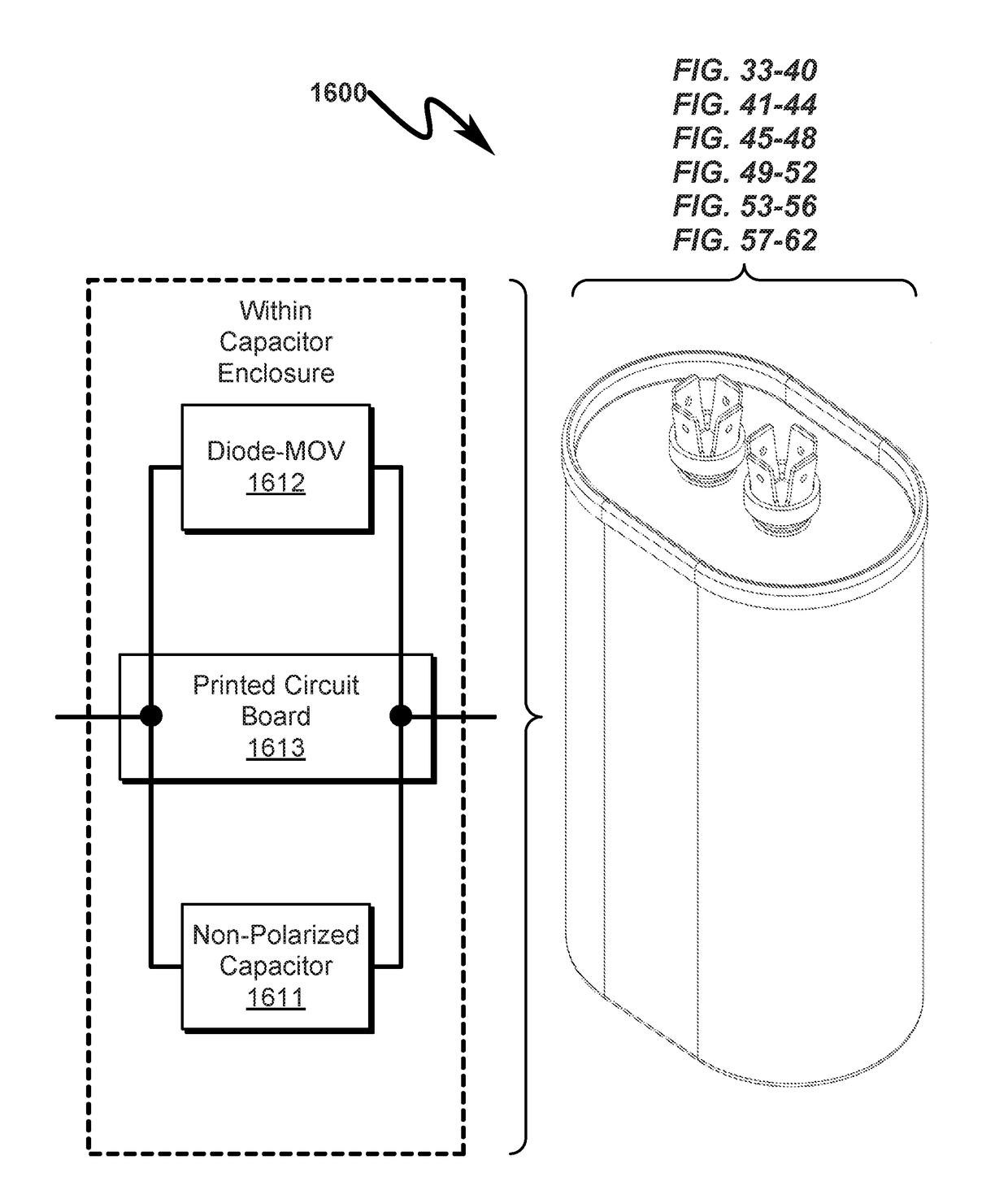
[0151]The present invention preferred exemplary method embodiment can be generalized as protected capacitor retrofit method wherein the method utilizes a protected capacitor system comprising:

[0152](a) non-polarized capacitor (NPC);

[0153](b) printed circuit board (PCB);

[0154](c) transient voltage surge suppressor (TVS); and

[0155](d) semiconductor PN diode (PND);

[0156]wherein:

[0157]the NPC comprises a capacitor enclosure (CPE) and a capacitor cover (CPC);

[0158]the NPC comprises a first capacitor connection (FTC) and a second capacitor connection (STC);

[0159]the TVS compress a first TVS connection (FVC) and a second TVS connection (SVC);

[0160]the PND comprises a first PND connection (FPC) and a second PND connection (SPC);

[0161]the SVC is electrically coupled to the FPC via metal traces on the PCB;

[0162]the TVS and the PND form a surge suppression device (SSD) having a first SSD terminal (FDC) electrically coupled to the FVC and a second SSD terminal...


PUM


Abstract

A protected capacitor system/method implementing enhanced transient over-voltage suppression is disclosed. The system/method incorporates one or more surge suppression devices (SSDs) proximally located and in parallel with a capacitor structure to produce an overall protected capacitor structure having enhanced reliability and simultaneous ability to resist transient overvoltage conditions. The SSDs are formed from series combinations of transient voltage surge suppressors (TVSs) (metal oxide varistor (MOV), diode for alternating current (DIAC), and/or silicon diode for alternating current (SIDAC)) and corresponding shunt diode rectifiers (SDRs) and placed in parallel across a capacitor structure to locally suppress voltage transients across the capacitor structure in excess of the voltage rating of the capacitor structure. The parallel shunting TVB/SDR pairs may be integrated into a printed circuit board (PCB) assembly that is externally attached to the capacitor structure or encapsulated in an enclosure incorporating the capacitor structure.

Description

CROSS REFERENCE TO RELATED APPLICATIONSParent Application[0001]This is a Continuation-In-Part patent application (CIP) of U.S. Utility patent application for ELECTRICAL WIRING SYSTEM AND METHOD by inventor Mark E. Goodson, filed electronically with the USPTO on Jul. 1, 2015, with Ser. No. 14 / 789,270, EFS ID 22802725, confirmation number 7696, docket AXITH.0101CIP1-C, issued as U.S. Pat. No. 9,634,474 on Apr. 25, 2016.U.S. Utility Patent Applications[0002]This application claims benefit under 35 U.S.C. §120 and incorporates by reference U.S. Utility patent application for ELECTRICAL WIRING SYSTEM AND METHOD by inventor Mark E. Goodson, filed electronically with the USPTO on Jul. 1, 2015, with Ser. No. 14 / 789,270, EFS ID 22802725, confirmation number 7696, docket AXITH.0101CIP1-C, issued as U.S. Pat. No. 9,634,474 on Apr. 25, 2016.[0003]U.S. Utility patent application for ELECTRICAL WIRING SYSTEM AND METHOD by inventor Mark E. Goodson, filed electronically with the USPTO on Jul. 1, 20...

Claims


Application Information

Patent Timeline
IPC IPC(8): H01G4/002H02P29/032H01C7/12H02K11/20H01G4/224H01G4/228
CPCH01G4/002H01G4/224H02P29/032H01C7/12H02K11/20H01G4/228H02H3/165H02H9/005H02H9/04H02H9/041H02H9/043H02H9/044
Inventor GOODSON, MARK EUGENE
Owner MJG INNOVATIONS LLC
Why Eureka
Try Eureka