Joining of light metal alloy workpieces to steel workpieces using resistance spot welding and adhesive

Active Publication Date: 2017-08-17
GM GLOBAL TECH OPERATIONS LLC
View PDF11 Cites 14 Cited by
  • Summary
  • Abstract
  • Description
  • Claims
  • Application Information

AI Technical Summary

Benefits of technology

[0005]A method of adhesive weld bonding a light metal workpiece and a steel workpiece together may have several steps according to one embodiment of the disclosure. First, a light metal workpiece having a faying surface and a steel workpiece having a faying surface is provided. Second, a plurality of discrete adhesive ribbons is applied to the faying surface of the light metal workpiece, the faying surface of steel workpiece, or the faying surfaces of both the light metal workpiece and the steel workpiece. Third, the light metal workpiece and the steel workpiece together are assembled together in overlapping fashion such that their faying surfaces establish a faying interface. Moreover, during assembly of the light metal and steel workpieces, the discrete adhesive ribbons are spread out laterally between the faying surface of the light metal workpiece and the faying surface of the steel workpiece so that a plurality of adhesive free zones are established amongst one or more adhesive zones. Fourth, a resistance spot weld that bonds the light metal workpiece and the steel workpiece together is formed at a spot weld location within one of the adhesive free zones. The formed spot weld comprises a weld joint contained within the light metal workpiece that bonds to the faying interface of the steel workpiece.
[0006]Practices of the aforementioned embodiment may be further defined. For instance, the light metal workpiece may be an aluminum alloy workpiece. As another example, a plurality of resistance spot welds may be formed between the light metal workpiece and the steel workpiece. In that regard, each of the plurality of spot welds is formed at a spot weld location within one of the plurality of adhesive free zones. Still further, the plurality of discrete adhesive ribbons may comprises a plurality of discrete adhesive ribbons in the form of elongated strips that are deposited along a weld line that extends through and connects a plurality of spot weld locations when the light metal workpiece and the steel workpiece are assembled in overlapping fashion. This same plurality of discrete adhesive ribbons may further include, if desired, a discrete adhesive ribbon in the form of an elongated strip that is laterally displaced from the weld line and extends alongside one of the spot weld locations. And in yet another example, the plurality of discrete adhesive ribbons may comprise a plurality of discrete adhesive ribbons in the form of annuluses, with each annulus of adhesive surrounding a spot weld location. In whatever form the adhesive ribbons may assume, each of the ribbons may have a width ranging from 2 mm to 10 mm, a height ranging from 0.2 mm to 2 mm, and a length ranging from 20 mm to 200 mm.
[0007]A method of adhesive weld bonding a light metal workpiece and a steel workpiece together may have several steps according to another embodiment of the disclosure. First, a plurality of discrete adhesive ribbons are applied to a faying surface of a first metal workpiece such that none of the adhesive ribbons intrude into any of a plurality of spot weld locations of

Problems solved by technology

The joining of these dissimilar metals by resistance spot welding is itself challenging due to their markedly different physical properties (e.g., melting point, thermal conductivity, electrical conductivity, strength at elevated temperatures, etc.) a

Method used


Image

  • Joining of light metal alloy workpieces to steel workpieces using resistance spot welding and adhesive
  • Joining of light metal alloy workpieces to steel workpieces using resistance spot welding and adhesive
  • Joining of light metal alloy workpieces to steel workpieces using resistance spot welding and adhesive

Examples


Embodiment Construction

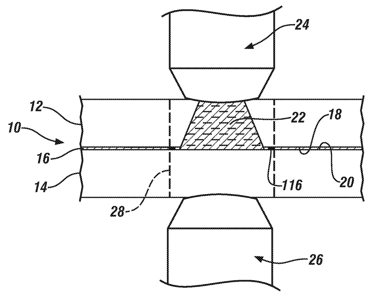
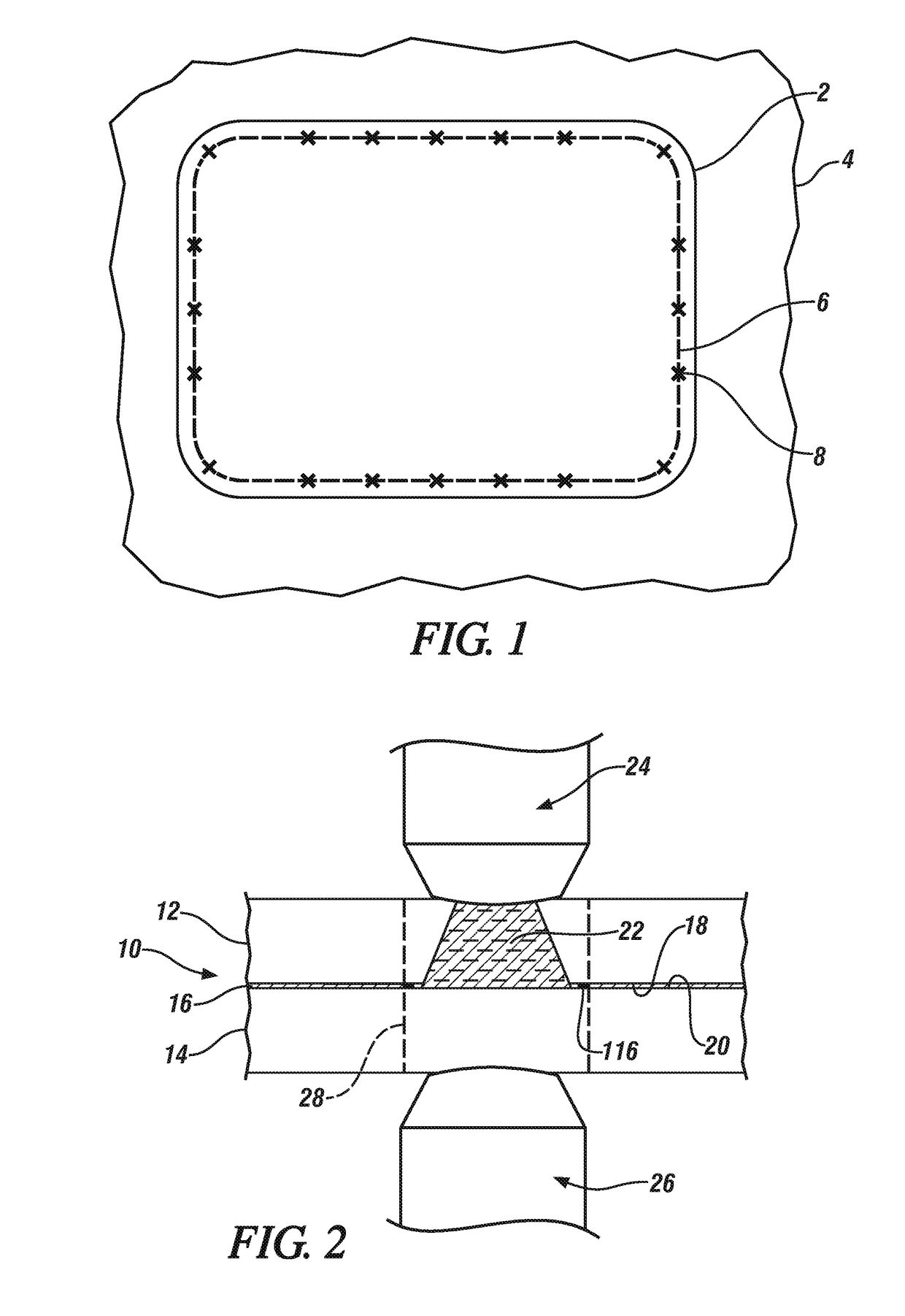
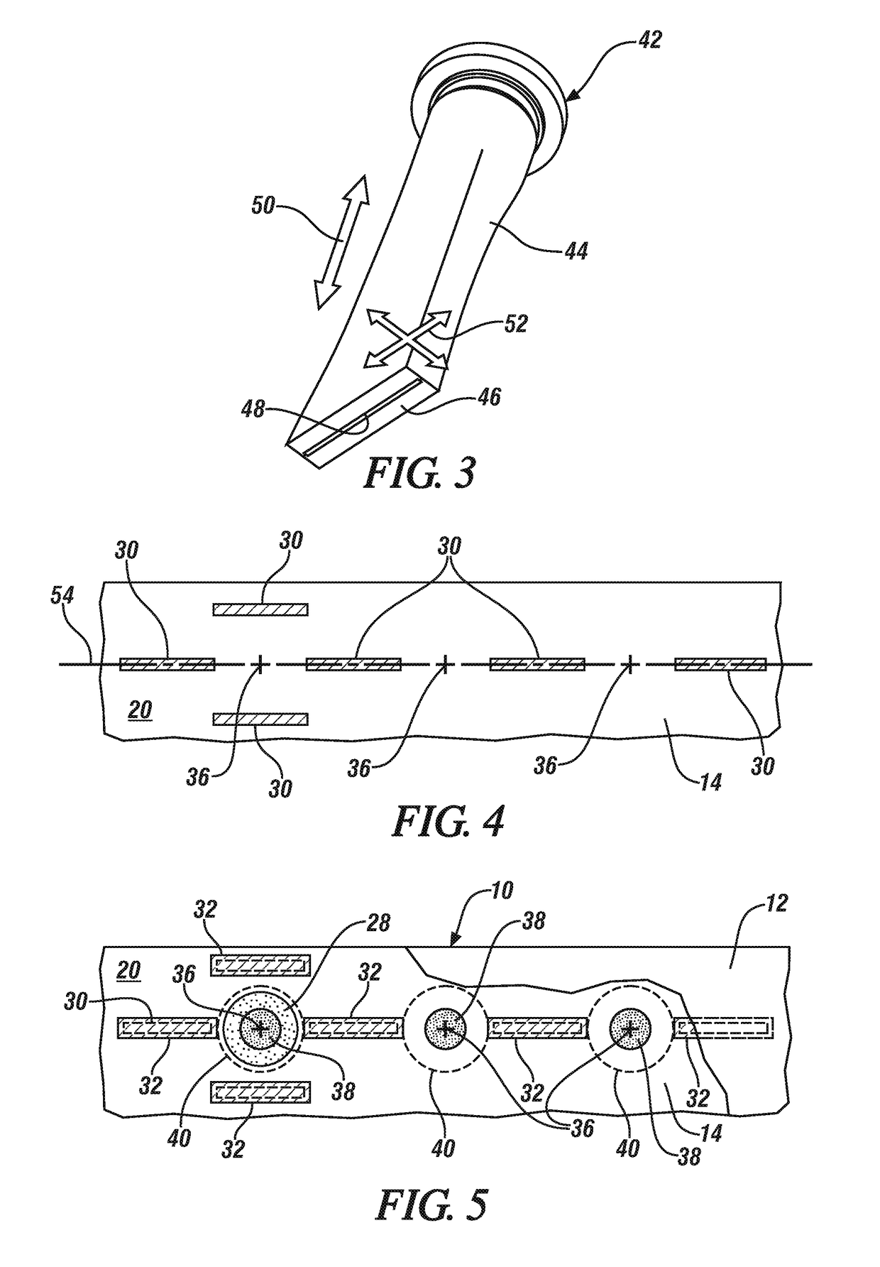
[0016]The present disclosure involves a method for joining a steel workpieces to a light metal workpiece such as, for example, an aluminum alloy workpiece or a magnesium alloy workpiece. The disclosed procedure uses adhesive weld bonding which, as previously described, is a combination of resistance spot welding and adhesive bonding, to securely join the workpieces together at a joining region such as overlapping flanges. Resistance spot welding is practiced at one or more designated spot weld locations and adhesive bonding is relied on to adhere portions of the workpieces together between the spot weld locations. The term “spot weld location” as used herein refers to the portions of the light metal workpiece and the steel workpieces that are engaged under pressure by welding electrodes and which are ultimately bonded together by a spot weld, which comprises a weld joint contained within the light metal workpieces, derived from passing electrical current between the electrodes. The ...


PUM

PropertyMeasurementUnit
Widthaaaaaaaaaa
Widthaaaaaaaaaa
Widthaaaaaaaaaa

Abstract

A method of adhesive weld bonding a light metal workpiece and a steel workpiece is disclosed that includes applying a plurality of discrete adhesive ribbons to a faying surface of the light metal workpiece, the faying surface of the steel workpiece, or both faying surfaces, and then assembling the workpieces together to establish one or more adhesive zones between the faying surfaces of the light metal and steel workpieces and a plurality of adhesive free zones amongst the adhesive zone(s). The method further includes forming a resistance spot weld that bonds the the light metal workpiece and the steel workpiece together at a spot weld location within one of the adhesive free zones. The formed spot weld includes a weld joint contained within the light metal workpiece that bonds to the faying interface of the steel workpiece.

Description

CROSS-REFERENCE TO RELATED APPLICATION(S)[0001]This application claims the benefit of U.S. Provisional Application No. 62 / 295,609, which was filed on Feb. 16, 2016. The aforementioned provisional application is incorporated herein by reference in its entirety.INTRODUCTION[0002]Resistance spot welding finds broad application in welding thin—typically less than 6 millimeter thick—metal workpieces together across a variety of manufacturing industries. For example, resistance spot welding is widely used in the construction and fabrication of automotive assemblies including structural components such as rocker panels or B pillars. Additionally, “hang-on” parts such as doors, decklids, and hoods usually comprise an aesthetically-pleasing outer panel, visible to an observer outside the vehicle, coupled at its periphery to an inner panel, which is hidden from view and often obscured by a plastic or fabric covering. Such hang-on parts frequently incorporate structural features or members—suc...

Claims


Application Information

Patent Timeline
IPC IPC(8): B23K11/20B23K11/34C09J5/10B23K11/11
CPCB23K11/20B23K11/115B23K11/34C09J2400/163B23K2203/20C09J2463/00C09J5/10B23K2103/20C09J5/06
Inventor CARLSON, BLAIR E.SIGLER, DAVID R.
Owner GM GLOBAL TECH OPERATIONS LLC
Why Eureka
Try Eureka