
Backup system for supplying compressed air to a gas turbine component

a gas turbine and compressed air technology, applied in combination engines, machines/engines, mechanical equipment, etc., can solve problems such as adversely affecting the efficiency of gas turbine engines, and achieve the effect of improving the overall reliability of the cooling system

Active Publication Date: 2017-08-17
POWERPHASE
View PDF2 Cites 4 Cited by
  • Summary
  • Abstract
  • Description
  • Claims
  • Application Information

AI Technical Summary

Benefits of technology

The present invention relates to systems and methods for improving cooling of a gas turbine engine's turbine section. The invention provides a primary source of cooling air through an auxiliary compression system and a secondary source of cooling air through an electric backup compression system. The invention also includes a method for allowing the gas turbine engine to continue operating at full power when the auxiliary compression system stops operating. Additionally, the invention includes a method for using all-electric systems to replace the separately fueled auxiliary compression system for air injection. The invention also includes a method for using all-electric way of taking gas turbine compressor discharge air in a mixing process to add heat to the air being delivered from the electric-driven intercooled air compressor. The technical effects of the invention include improved cooling of gas turbine engine components, increased efficiency of the gas turbine engine, and reduced emissions.

Problems solved by technology

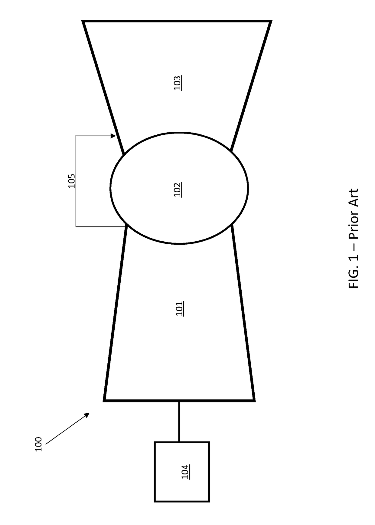
However, removing air 105 from the compressor 101 reduces the amount of air which goes through the combustion process, thereby adversely affecting gas turbine engine efficiency.

Method used


Image

  • Backup system for supplying compressed air to a gas turbine component
  • Backup system for supplying compressed air to a gas turbine component
  • Backup system for supplying compressed air to a gas turbine component

Examples


Embodiment Construction

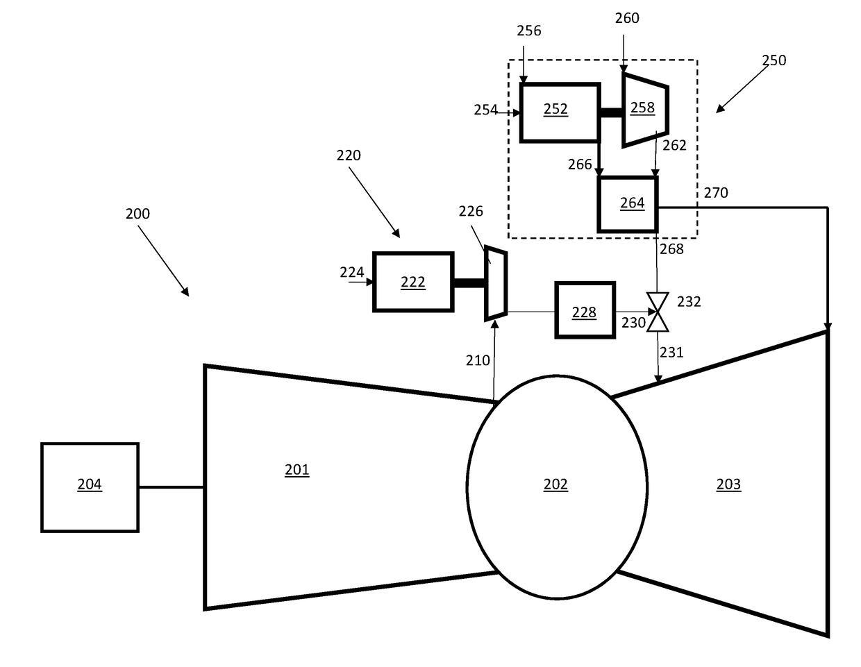
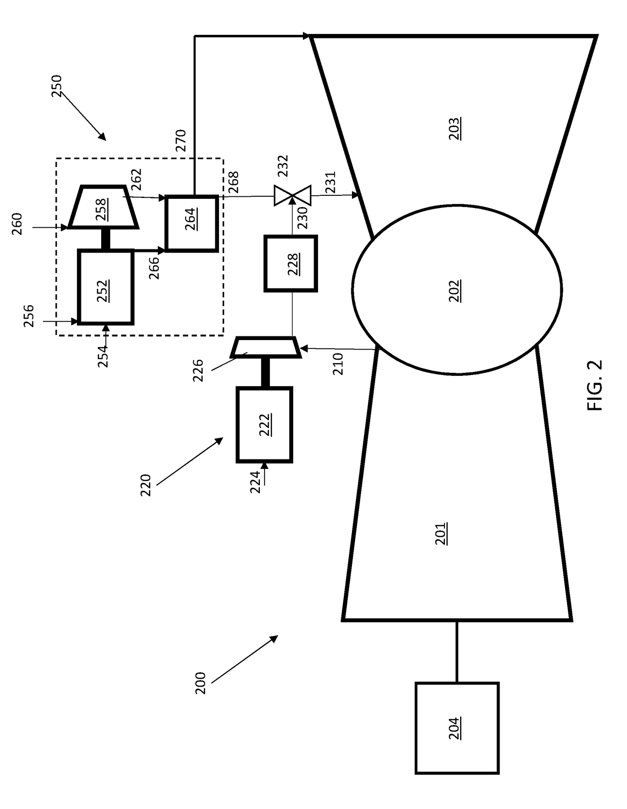
[0022]Embodiments of the present invention are described below with respect to FIGS. 2-4. Referring initially to FIG. 2, a gas turbine engine 200 is provided comprising a compressor 201, a combustion system 202, and a turbine 203 in fluid communication. The compressor 201 takes in ambient air and compresses it, through a multi-stage compression process, to a higher temperature and pressure and passes the compressed air to the combustion system 202. A portion of the compressed air 210 is directed from the compressor discharge for purposes of cooling components in the turbine 203.

[0023]The compressed air 210 is passed to an electric backup compression system 220 that is also in fluid communication with the turbine 203. The electric backup compression system 220 comprises a motor 222 powered by an electrical supply 224. The motor 222 provides shaft power to turn the backup compressor 226. This electric backup compression system 220 takes compressed air 210 from the engine compressor 20...


PUM


Abstract

The invention relates generally to gas turbine engines used for electrical power generation. More specifically, embodiments of the present invention provide systems and ways for improving gas turbine engine reliability through an electric motor backup system for cooling features of the turbine section.

Description

CROSS-REFERENCE TO RELATED APPLICATIONS[0001]This application claims priority to U.S. Provisional Patent Application Ser. No. 62 / 293,887, filed on Feb. 11, 2016, which is hereby incorporated by reference in its entirety.TECHNICAL FIELD[0002]The invention relates generally to electrical power systems, including generating capacity of a gas turbine, and more specifically to systems and methods for providing an efficient and more reliable way of cooling engine components.BACKGROUND OF THE INVENTION[0003]Gas turbine engines are commonly used in land-based power plants for generating electricity. A representative simple cycle gas turbine engine 100 is shown in FIG. 1. These land-based power plants take atmospheric air into a compressor 101, increase its pressure through a compression process, mix fuel with the compressed air and ignite the mixture to generate hot combustion gases through one or more combustors 102, which drive a turbine 103 that is coupled to the compressor 101. The mech...

Claims


Application Information

Patent Timeline
Patent Type & Authority Applications(United States)
IPC IPC(8): F02C7/18H02K7/18
CPCF02C7/185H02K7/1823F05D2270/3062F05D2260/232F05D2260/211F01D13/02F02C6/06F02C7/12F02C7/16
Inventor KRAFT, ROBERT J.
Owner POWERPHASE
Learn More