Mask inspection apparatus and mask inspection method

a mask and inspection apparatus technology, applied in the field of mask inspection apparatus, can solve the problems of reducing reflectance, stains are easily deposited on reflective surfaces, and the shape of the mask cannot be accurately recognized, so as to prevent the reduction of the reflectance of the drop-in mirror

Active Publication Date: 2017-08-17
LASERTEC CORP
View PDF4 Cites 5 Cited by
  • Summary
  • Abstract
  • Description
  • Claims
  • Application Information

AI Technical Summary

Benefits of technology

[0024]A mask inspection apparatus according to the present invention includes a drop-in mirror including: a multi-layer film; and a reflective surface. The drop-in mirror is configured to reflect illumination light incident on the reflective surface and illuminate a mask, an area of the reflective surface is configured to be greater than an area of an illuminated spot irradiated with the illumination light on the reflective surface, the drop-in mirror is configured to be movable, and a position of the illuminated spot on the reflective surface is configured to be moved when the drop-in mirror is moved. With such a configuration, it is possible to prevent a reduction in a reflectance of the drop-in mirror, which is caused by stains such as carbon contaminants or the like.

Problems solved by technology

However, as defects are small, the shapes thereof cannot be accurately recognized by the magnification of about 26 times, which is made by the Schwarzschild optical system 904.
There is a problem that if the power of the EUV light is large, stains such as carbon compounds (carbon contaminants) or the like are attached to a reflective surface of a mirror that reflects the EUV light, thereby reducing the reflectance.
The problem is that stains are easily deposited on reflective surfaces of the drop-in mirrors 903a and 903b. The stains contain, for example, carbon compounds.
These stains reduce the reflectance of EUV light and reduce the power of reflected light.
In particular, the greater the intensity of the EUV light that is incident on the reflective surfaces, the greater the speed at which stains such as carbon contaminants or the like are generated will become.
As described above, there has been a problem in the mask inspection apparatus that stains such as carbon contaminants or the like are generated on the drop-in mirror 903a in a short time.
Therefore, inspections are more susceptible to the influence of an environment such as one with vibrations and the like during the long exposure time.
However, when the power of the illumination light is increased, there has been a problem that stains such as carbon contaminants or the like are generated in a shorter time, and thus the reflective surfaces need to be frequently cleaned.
However, in this method, EUV light with extremely high power is necessary in order to generate hydrogen radicals, and thus it has been difficult to employ this method for an inspection apparatus for masks with a power of EUV light that is low by an order(s) of magnitude.

Method used


Image

  • Mask inspection apparatus and mask inspection method
  • Mask inspection apparatus and mask inspection method
  • Mask inspection apparatus and mask inspection method

Examples


first exemplary embodiment

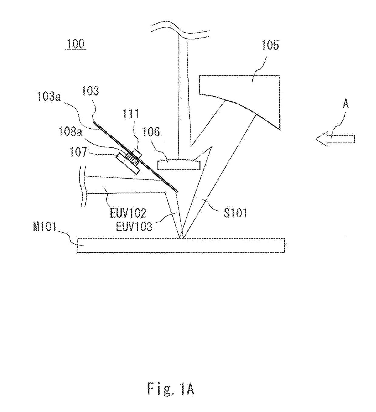
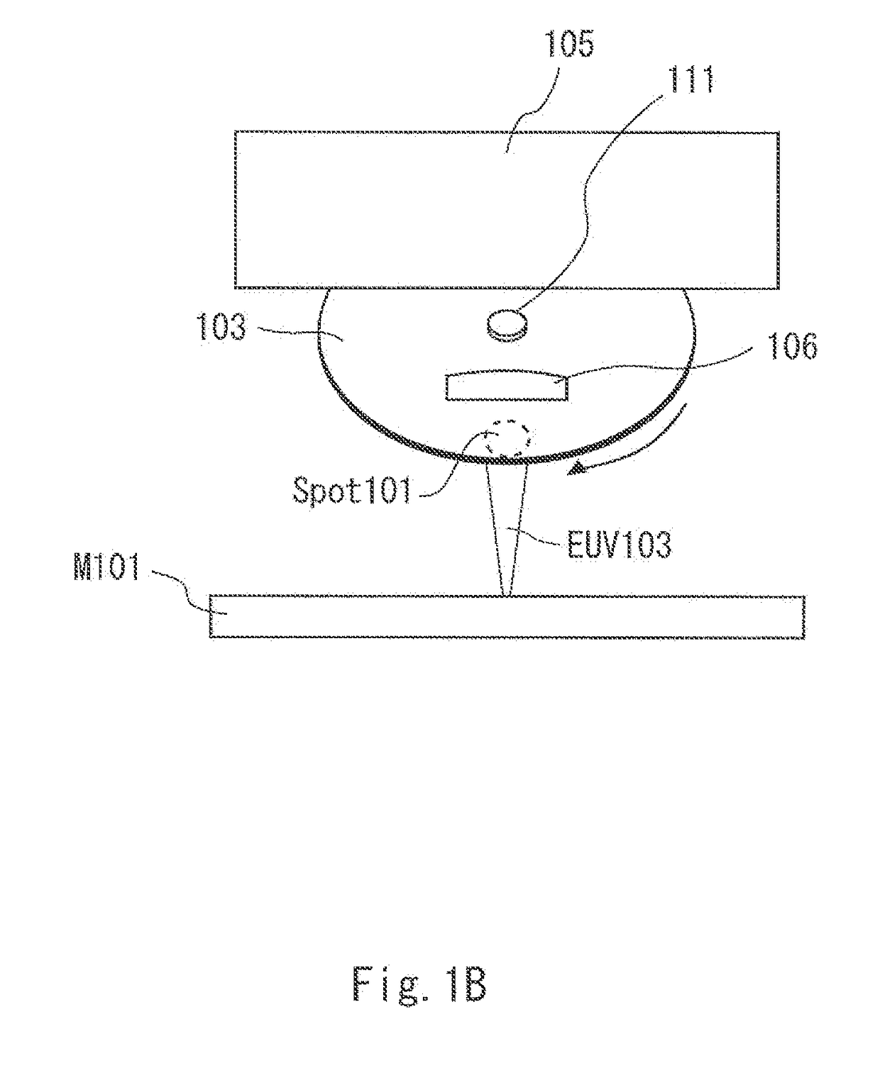
[0057]This exemplary embodiment relates to an exemplary embodiment of a mask inspection apparatus. Firstly, a configuration of the mask inspection apparatus according to this exemplary embodiment will be described. FIG. 1A is a cross-sectional diagram showing an example of the mask inspection apparatus according to a first exemplary embodiment, and FIG. 1B is a drawing in which the mask inspection apparatus is seen from a direction A in FIG. 1A.

[0058]As shown in FIGS. 1A and 1B, a mask inspection apparatus 100 includes a drop-in mirror 103, a concave mirror 105, and a convex mirror 106. The mask inspection apparatus 100 further includes an EUV light source, a CCD (Charge Coupled Device) detector, and other optical elements, which are not shown. As the configuration including the EUV light source shown in FIGS. 1A and 1B except for the optical elements is the same as the configuration of the ABI apparatus 900 shown in, for example, FIGS. 10 and 11, it is not shown in FIGS. 1A and 1B....

modified example

[0075]Next, a mask inspection apparatus according to a modified example of the first exemplary embodiment will be described. FIG. 4A is a cross-sectional diagram showing an example of the mask inspection apparatus according to the modified example of the first exemplary embodiment, and FIG. 4B is a drawing in which the mask inspection apparatus is seen from a direction B in FIG. 4A.

[0076]As shown in FIGS. 4A and 4B, a drop-in mirror 1103 of a mask inspection apparatus 100a is a plate-like member that is extended in a direction vertical to a surface including an optical axis of the illumination light EUV102 that is incident on the reflective surface 1103a and an optical axis of the illumination light EUV103 that is reflected by the reflective surface 1103a. The drop-in mirror 1103 can be moved in the direction in which the drop-in mirror 1103 is extended.

[0077]As shown in FIGS. 4A and 4B, the mask inspection apparatus 100a includes the drop-in mirror 1103, the concave mirror 105, and...

second exemplary embodiment

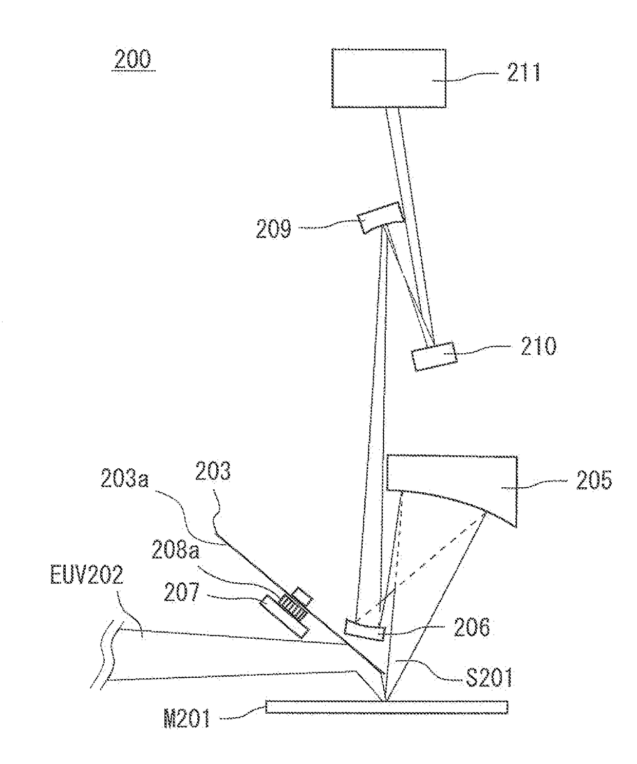
[0083]Next, a mask inspection apparatus according to a second exemplary embodiment will be described. FIG. 5 is a cross-sectional diagram showing the mask inspection apparatus according to the second exemplary embodiment. As shown in FIG. 5, a mask inspection apparatus 200 is for inspecting a mask M201. The mask inspection apparatus 200 is a projection optical system that includes four multi-layer mirrors in total, which are: a concave mirror 205 (a first concave mirror), a concave mirror 206 (a second concave mirror), a concave mirror 209, and a planar mirror 210. The mask inspection apparatus 200 further includes other optical elements, which are: a drop-in mirror 203, a CCD detector 211, a light source (not shown), and optical elements that constitute an illumination optical system (not shown).

[0084]The concave mirror 205 is disposed to face the mask surface side of the mask M201 and be distant from the mask surface. A reflective surface of the concave mirror 205 faces the mask M...


PUM


Abstract

Provided are a mask inspection apparatus and a mask inspection method that can prevent a reduction in a reflectance of a drop-in mirror, which is caused by carbon contaminants. A mask inspection apparatus according to the present invention includes a drop-in mirror including multi-layer film and a reflective surface. The drop-in mirror is configured to reflect illumination light incident on the reflective surface and illuminate the mask. An area of the reflective surface is configured to be greater than an area of an illuminated spot irradiated with the illumination light on the reflective surface. The drop-in mirror is configured to be movable. A position of the illuminated spot on the reflective surface is configured to be moved when the drop-in mirror is moved.

Description

CROSS REFERENCE TO RELATED APPLICATIONS[0001]The present application claims priority to Japanese Patent Application No. 2016-024904, filed on Feb. 12, 2016, and Japanese Patent Application No. 2016-024905, filed on Feb. 12, 2016. The entire contents of the above-referenced applications are hereby incorporated by reference in their entirety for all purposes.BACKGROUND OF THE INVENTION[0002]1. Field of the Invention[0003]The present invention relates to a mask inspection apparatus for EUVL (Extremely Ultraviolet Lithography), and in particular, to a mask inspection apparatus and a mask inspection method called an Actinic inspection that uses EUV light with a wavelength of 13.5 nm, which is the same as an exposure wavelength, as illumination light.[0004]2. Description of Related Art[0005]In the lithography technology for miniaturizing semiconductors, currently the ArF lithography that uses an ArF excimer laser with an exposure wavelength of 193 nm as an exposure light source is employe...

Claims


Application Information

Patent Timeline
Patent Type & Authority Applications(United States)
IPC IPC(8): G02B5/08B08B7/00G02B19/00G02B17/00G02B5/18G02B7/182
CPCG02B5/0891G02B5/0816G02B5/1838B08B7/0057G02B7/1821G02B19/0095G02B17/004G02B5/1814B08B7/0042G01N21/958G02B5/1861G02B19/0004G02B27/425G02B27/4294G01N21/00G01N21/88
Inventor TAKEHISA, KIWAMUMIYAI, HIROKI
Owner LASERTEC CORP
Why Eureka
Try Eureka