Biological information measurement apparatus and biological information measurement method

a technology of biological information and measurement apparatus, which is applied in the field of biological information measurement technology, can solve problems such as difficulty in and achieve the effect of reducing the size of the apparatus

Inactive Publication Date: 2017-09-07
SEIKO EPSON CORP
View PDF10 Cites 12 Cited by
  • Summary
  • Abstract
  • Description
  • Claims
  • Application Information

AI Technical Summary

Benefits of technology

[0006]An advantage of some aspects of the invention is to reduce the size of an apparatus that measures a pulse wave propagation velocity.
[0008]In this configuration, the biological information measurement apparatus obtains a pulse wave propagation velocity from a change over time in blood flow rate and a change over time in blood vessel cross-sectional area. Therefore, it is not necessary for a subject to wear sensors on multiple measurement sites such as a finger and a wrist, the number of measurement sites may be one, and the number of sensors (an irradiation unit and a detection unit) for measurement may be one. As a result, it is possible to reduce the size of the biological information measurement apparatus.
[0013]In the biological information measurement apparatus according to the first or second aspect of the invention, the irradiation unit may include a first irradiation unit configured to irradiate the living body with laser beams, and a second irradiation unit configured to irradiate the living body with non-laser beams, the detection unit may include a first detection unit configured to detect the laser beams having passed through the inside of the living body, and a second detection unit configured to detect the non-laser beams having passed through the inside of the living body, and the computational unit may obtain a change over time in blood flow rate based on a detection result from the first detection unit, and obtains a change over time in blood vessel cross-sectional area based on a detection result from the second detection unit (sixth aspect). In this case, the biological information measurement apparatus obtains a change over time in blood flow rate via measurement using laser beams, and obtains a change over time in blood vessel cross-sectional area via measurement using non-laser beams. Accordingly, it is possible to accurately obtain the change over time in blood flow rate and the change over time in blood vessel cross-sectional area. As a result, it is possible to improve the accuracy of computation of a pulse wave propagation velocity.
[0014]In the biological information measurement apparatus according to the first or second aspect of the invention, the irradiation unit may include a first irradiation unit configured to irradiate the living body with laser beams, and a second irradiation unit configured to irradiate the living body with non-laser beams, the detection unit may detect the laser beams and the non-laser beams having passed through the inside of the living body, and the computational unit may obtain a change over time in blood flow rate based on a result of detecting the laser beams via the detection unit, and obtains a change over time in blood vessel cross-sectional area based on a result of detecting the non-laser beams via the detection unit (seventh aspect). In this case, the number of detection units may be one, and it is not necessary to separately provide a detection unit for detecting laser beams and a detection unit for detecting non-laser beams. As a result, it is possible to further simplify the configuration of the biological information measurement apparatus and to further reduce the size of the biological information measurement apparatus than those of the biological information measurement apparatus of the sixth aspect of the invention.
[0015]In the biological information measurement apparatus according to the sixth or seventh aspect of the invention, a site of the living body, from which a change over time in blood flow rate is obtained by irradiating the site with laser beams, may be the same as a site of the living body from which a change over time in blood vessel cross-sectional area is obtained by irradiating the site with non-laser beams (eighth aspect). In this case, it is possible to obtain a pulse wave propagation velocity from the change over time in blood flow rate and the change over time in blood vessel cross-sectional area which are obtained from the same site. As a result, it is possible to accurately obtain a pulse wave propagation velocity of a local site (measurement site). Since a site from which a change over time in blood flow rate is obtained by irradiating the site with laser beams is the same as a site from which a change over time in blood vessel cross-sectional area is obtained by irradiating the site with non-laser beams, it is possible to further reduce the size of the biological information measurement apparatus than that of a biological information measurement apparatus in a case where both the sites are different.

Problems solved by technology

As a result, it is difficult to reduce the size of the apparatus.

Method used


Image

  • Biological information measurement apparatus and biological information measurement method
  • Biological information measurement apparatus and biological information measurement method
  • Biological information measurement apparatus and biological information measurement method

Examples


first embodiment

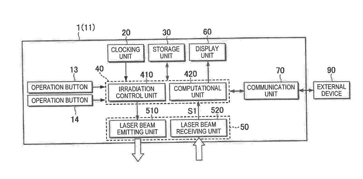
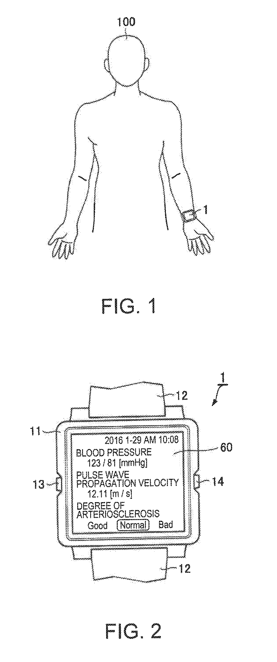
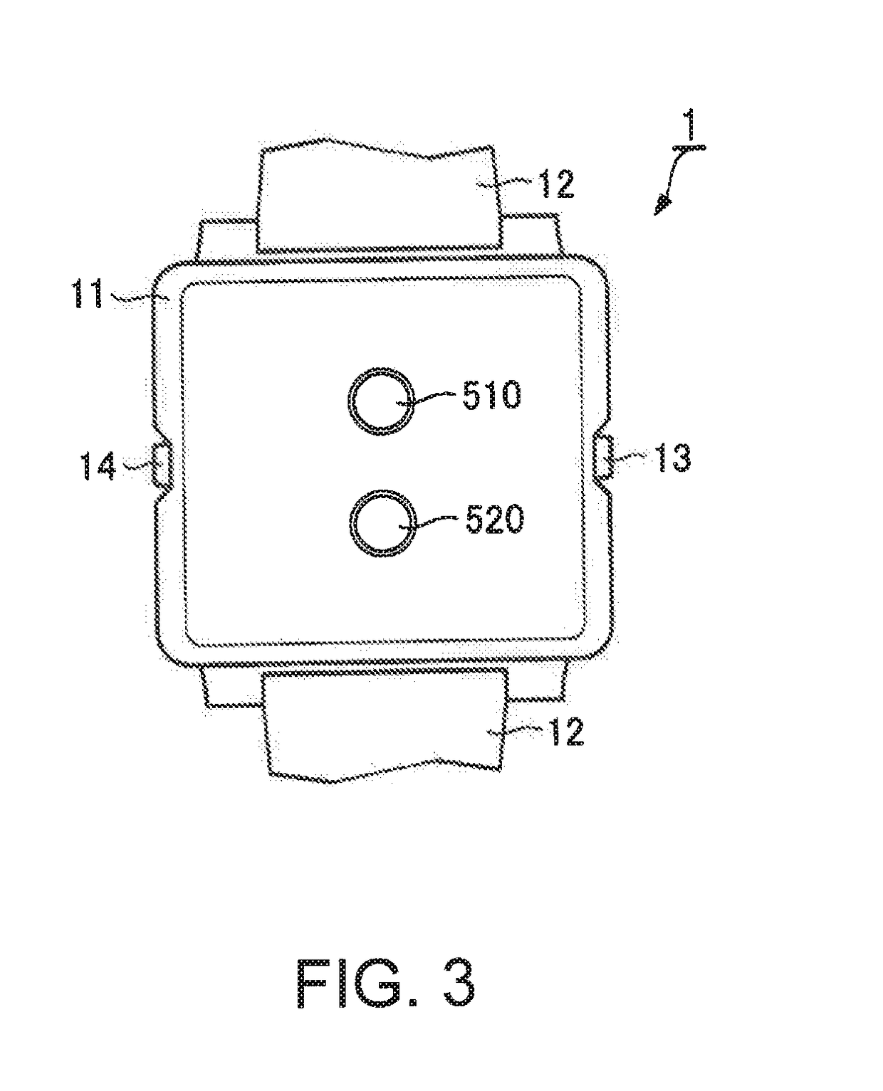
[0036]FIG. 1 is a view illustrating a state in which a subject 100 wears a biological information measurement apparatus 1 of a first embodiment of the invention on a wrist. FIG. 2 is a front view of the biological information measurement apparatus 1, and FIG. 3 is a rear view of the biological information measurement apparatus 1. The biological information measurement apparatus 1 is a measurement device that measures biological information regarding the subject (living body) 100 in a non-invasive manner. As illustrated in FIG. 1, the biological information measurement apparatus 1 is a wrist-watch type wearable device which the subject 100 wears on the wrist. The biological information measurement apparatus 1 is an optical blood pressure meter, and is capable of measuring a blood pressure or the degree of arteriosclerosis as biological information in addition to a pulse wave propagation velocity.

[0037]As illustrated in FIGS. 2 and 3, the biological information measurement apparatus 1...

second embodiment

[0065]FIG. 7 is a block diagram illustrating the inner configuration of a biological information measurement apparatus 2 of a second embodiment of the invention. In the embodiment, the reference signs used in the first embodiment are assigned to elements common to the first embodiment, and description thereof will be suitably omitted. The biological information measurement apparatus 2 of the second embodiment obtains a “change over time in the blood vessel cross-sectional area A”, which is used to calculate the pulse wave propagation velocity PWV, by a method different from the technique described in the first embodiment. The biological information measurement apparatus 2 of the second embodiment is capable of measuring a plethysmogram as biological information regarding the subject 100. Other portions of the biological information measurement apparatus 2 are the same as those of the biological information measurement apparatus 1 of the first embodiment apart from the aforementioned...

third embodiment

[0080]FIG. 11 is a block diagram illustrating the inner configuration of a biological information measurement apparatus 3 of a third embodiment of the invention. Also, in the embodiment, the reference signs used in the first embodiment are assigned to elements common to the first embodiment, and description thereof will be suitably omitted. The biological information measurement apparatus 3 of the third embodiment measures biological information regarding the subject 100 using light emitting diode (LED) beams instead of laser beams. The differences between the biological information measurement apparatus 3 illustrated in FIG. 11 and the biological information measurement apparatus 1 illustrated in FIG. 4 are that the biological information measurement apparatus 3 includes an irradiation control unit 412; an optical sensor 52 (an LED beam emitting unit 512 and an LED beam receiving unit 522); the received light signal S2; and a computational unit 424.

[0081]The irradiation control uni...


PUM


Abstract

A biological information measurement apparatus includes an irradiation unit configured to irradiate a living body with light or sound waves as measurement waves; a detection unit configured to detect the measurement waves having passed through the inside of the living body; and a computational unit configured to obtain a change over time in blood flow rate and a change over time in blood vessel cross-sectional area based on a detection result from the detection unit, and to obtain a pulse wave propagation velocity from the change over time in blood flow rate or the change over time in blood vessel cross-sectional area.

Description

BACKGROUND[0001]1. Technical Field[0002]The present invention relates to technology for measuring biological information.[0003]2. Related Art[0004]JP-A-2011-24676 discloses a pulse wave propagation velocity calculation apparatus, pulse wave sensors of which are mounted on at least two measurement sites such as a finger and a wrist, and which calculates a pulse wave propagation velocity using pulse waveforms detected by the pulse wave sensors.[0005]The pulse wave propagation velocity calculation apparatus disclosed in JP-A-2011-24676 calculates a pulse wave propagation velocity from a time difference in propagation of pulse waves between the measurement sites. For this reason, if the distance between the measurement sites is short, the accuracy of calculation of a pulse wave propagation velocity decreases. As a result, it is difficult to reduce the size of the apparatus.SUMMARY[0006]An advantage of some aspects of the invention is to reduce the size of an apparatus that measures a pu...

Claims


Application Information

Patent Timeline
Patent Type & Authority Applications(United States)
IPC IPC(8): A61B5/021A61B8/06A61B5/00A61B8/08A61B5/02A61B5/026A61B8/04
CPCA61B5/02125A61B5/0261A61B8/06A61B5/7278A61B8/5223A61B5/02007A61B5/681A61B8/04A61B5/0064A61B5/02108A61B8/4227A61B8/4427A61B2562/0233
Inventor SAWADO, AYAEMACHIDA, YUTA
Owner SEIKO EPSON CORP
Why Eureka
Try Eureka