Honeycomb structure
a honeycomb and structure technology, applied in the field of honeycomb structure, can solve the problem of prone to breakage in the boundary wall, and achieve the effect of reducing stress concentration, preventing deterioration of mechanical strength, and enhancing mechanical strength
- Summary
- Abstract
- Description
- Claims
- Application Information
AI Technical Summary
Benefits of technology
Problems solved by technology
Method used
Image

Examples
example 1
[0066]To a cordierite forming raw material of 100 pts. mass, a dispersing medium of 35 pts. mass, an organic binder of 6 pts. mass and a dispersing agent of 0.5 pts. mass were added, respectively, followed by mixing and kneading, to prepare a kneaded material. As the cordierite forming raw material, alumina, aluminum hydroxide, kaolin, talc, and silica were used. As the dispersing medium, water was used. As a pore former, cokes having an average particle diameter of 1 through 10 μm was used. As the organic binder, hydroxypropylmethyl cellulose was used. As the dispersing agent, ethylene glycol was used.
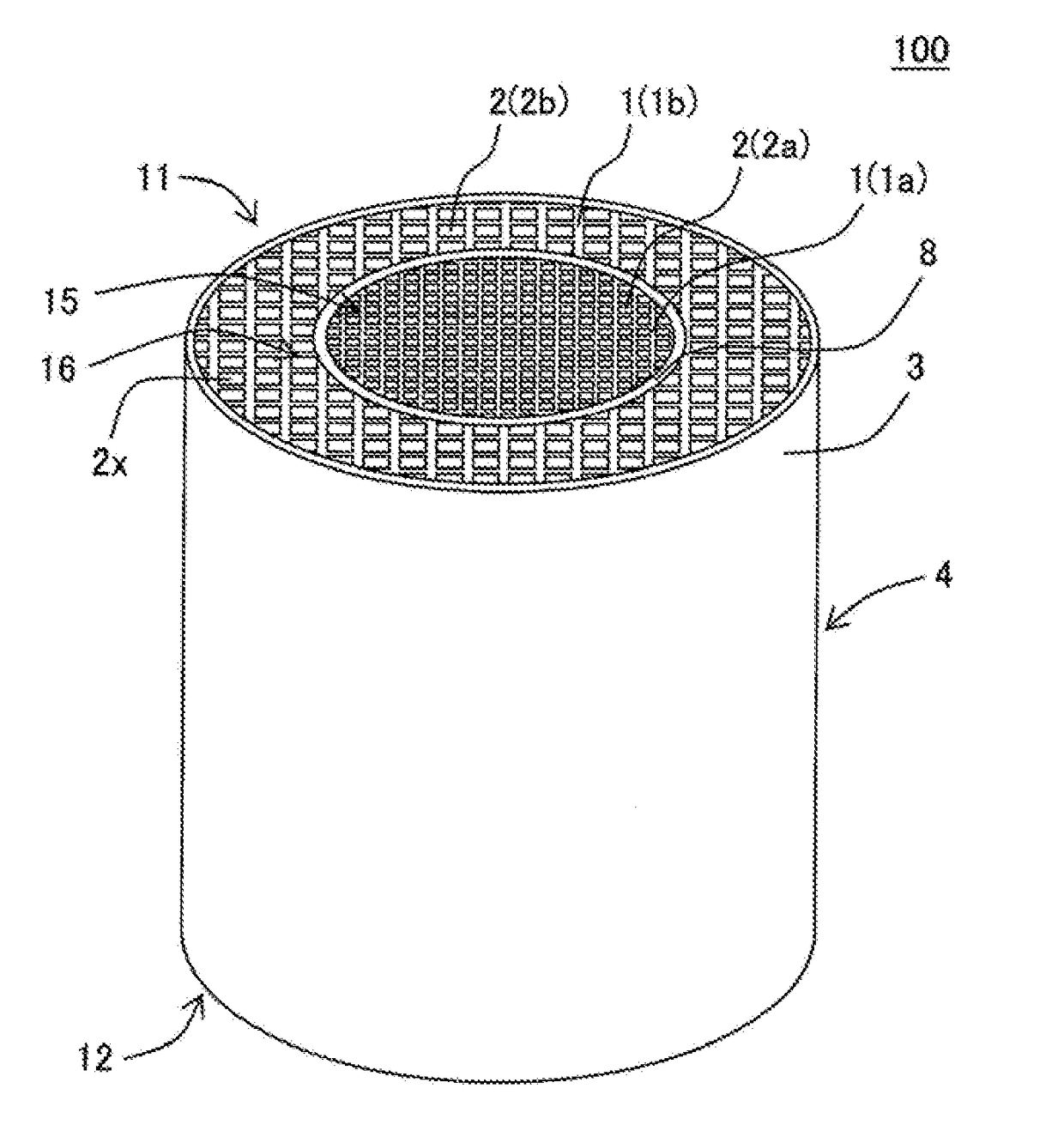
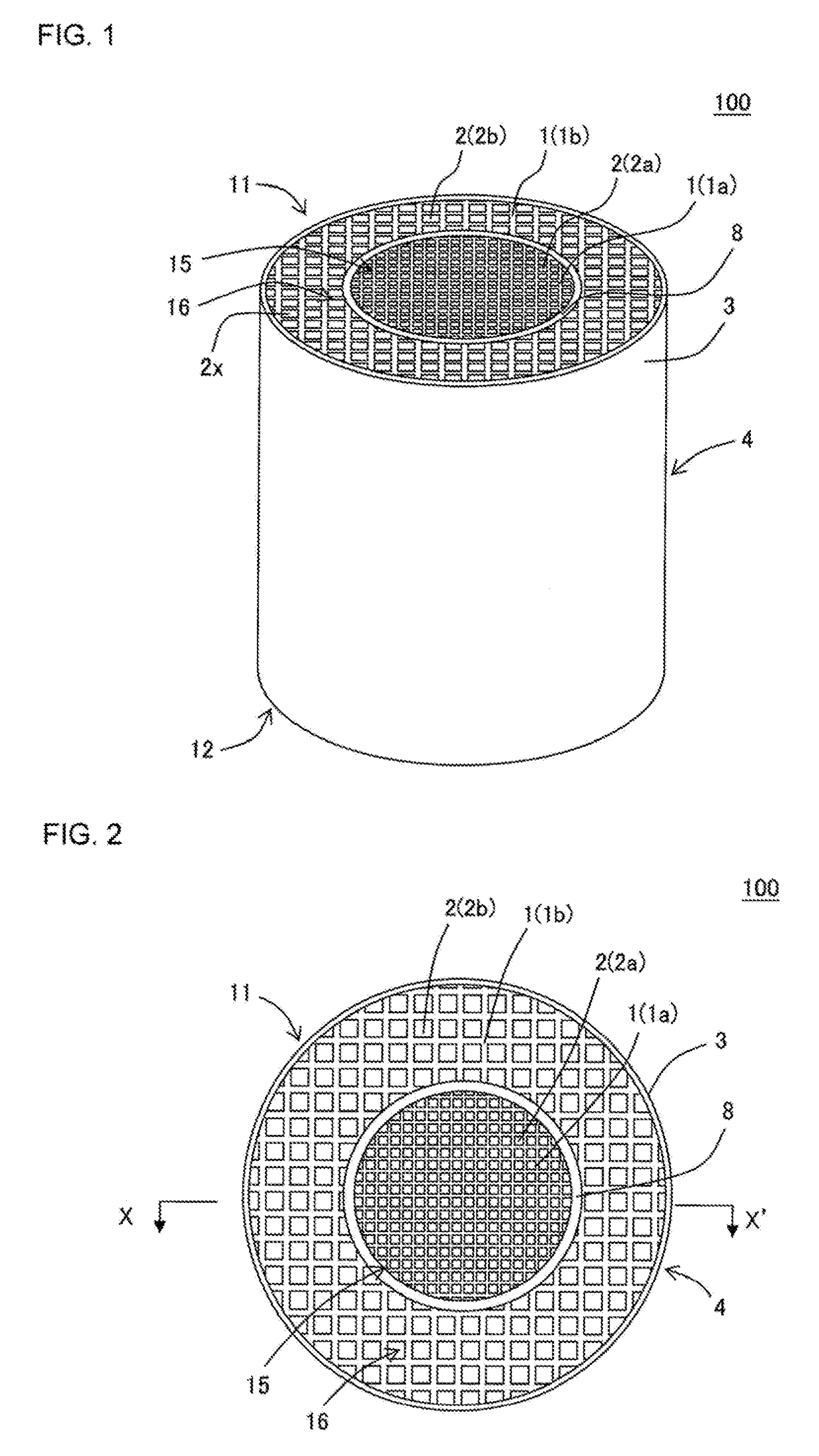
[0067]Next, the kneaded material was extruded by using a honeycomb formed body preparing die, to obtain a honeycomb formed body in which the whole shape was a round pillar shape. In the extrusion, the extruding die was used in which slits were formed so that a cell structure of a central portion of the honeycomb formed body to be extruded differed from a cell structure of a circumfere...
examples 2 through 23
, Comparative Examples 1 Through 6
[0085]Each of the honeycomb structures of the examples 2 through 23 and the comparative examples 1 through 6 was manufactured in accordance with “Kind of Cell Structure”, “existence or absence of boundary wall” and “Cell Structure” shown in Table 1 and “Thickness of Boundary Wall” shown in Table 2.
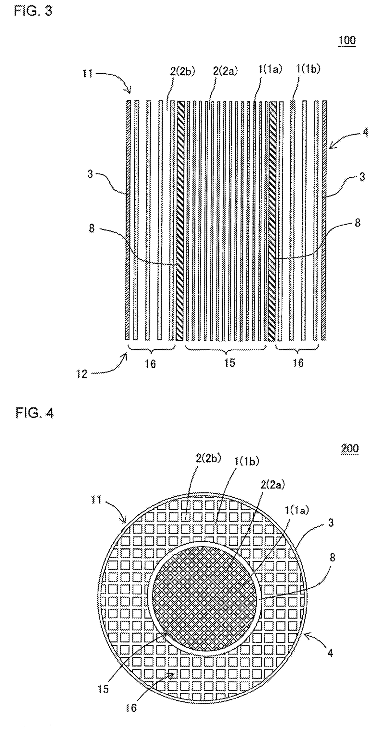
[0086]In each of the examples 7, 8, 16 and the comparative examples 4, 5, the center cell structure had “First Center Cell Structure” and “Second Center Cell Structure” as shown in FIG. 1. Further, the first center cell structure had a circular shape at the end face of the honeycomb structure body, and the diameter thereof was 68 mm. The second center cell structure had a circular shape at the end face of the honeycomb structure body, and the diameter thereof was 96 mm. In each of the examples 7, 8, 16 and the comparative examples 4, 5, the thickness of the center boundary wall was also measured. Further, “the ratio (%) of the thickness of the center bound...
examples 24 through 36
, Comparative Examples 7 Through 10
[0089]Each of the honeycomb structures of the examples 24 through 36 and the comparative examples 7 through 10 was manufactured in accordance with “Kind of Cell Structure”, “existence or absence of boundary wall” and “Cell Structure” shown in Table 3 and “Thickness of Boundary Wall” shown in Table 4.
[0090]In each of the examples 28, 29, 33 and the comparative examples 9, 10, the center cell structure had “First Center Cell Structure” and “Second Center Cell Structure” as shown in Table 3. Further, the first center cell structure had a circular shape at the end face of the honeycomb structure body, and the diameter thereof was 68 mm. The second center cell structure had a circular shape at the end face of the honeycomb structure body, and the diameter thereof was 96 mm.
[0091]Further, in each of the examples 31 through 33, “the incline (°) of the cell arrangement of the first center cell structure” and “the incline (°) of the cell arrangement of the ...
PUM
| Property | Measurement | Unit |
|---|---|---|
| Fraction | aaaaa | aaaaa |
| Fraction | aaaaa | aaaaa |
| Angle | aaaaa | aaaaa |
Abstract
Description
Claims
Application Information
 - R&D
- Intellectual Property
- Life Sciences
- Materials
- Tech Scout
- Unparalleled Data Quality
- Higher Quality Content
- 60% Fewer Hallucinations
Browse by: Latest US Patents, China's latest patents, Technical Efficacy Thesaurus, Application Domain, Technology Topic, Popular Technical Reports.
© 2025 PatSnap. All rights reserved.Legal|Privacy policy|Modern Slavery Act Transparency Statement|Sitemap|About US| Contact US: help@patsnap.com