Plasma densification method

a plasma and densification technology, applied in plasma techniques, electrical equipment, electric discharge tubes, etc., can solve problems such as inefficiency, damage to parts and electric power supplies, and voltaic arcs that may occur, and achieve higher densification of plasma, avoid voltaic arc production, and increase the production of secondary electrons

Inactive Publication Date: 2017-09-28
SCHOLTZ E FONTANA CONSULTORIA LTDA ME
View PDF7 Cites 1 Cited by
  • Summary
  • Abstract
  • Description
  • Claims
  • Application Information

AI Technical Summary

Benefits of technology

[0022]Due to the limitations of the hitherto known methods for increasing and controlling the plasma ionization rate, the general objective of the present invention is to provide a method of plasma densification (i.e., higher degree of ionization) by means of increasing the emission of secondary electrons using a periodic electronic bombardment of the electrode, thus achieving several benefits such as: greater control in the heating of the plasma, allowing a significant increase in the temperature of the plasma; possibility of obtaining plasma over a wide range of pressure of the working gas; greater plasma stability, with suppression of voltaic arcs; control in the volume of the luminescent region of the plasma; possibility of generating plasma with low negative voltage in the cathode, on the order of tens or hundreds of volts; better plasma coupling to the part geometry; higher energy transfer rate from the electrodes to the plasma, among others, making the plasma generation very flexible, from the point of view of choice of process parameters and greatly increasing the possibilities of technological applications.
[0024]According to the invention, the method comprises the steps of: accelerating the primary electrons contained in the gas or in the ionized mass toward the surface of one of said electrodes by the polarization of said electrode by means of a short positive bias pulse and high voltage, during a sufficient time for producing the impact of the primary electrons, or at least part of them, against the surface of said electrode and from this ejecting secondary electrons; accelerating the secondary electrons and any other electrons in the vicinity of said electrode towards the luminescence region by polarizing said electrode by means of a longer negative pulse, smaller in voltage amplitude in relation to the positive one, with sufficient potential to collide the electrons with neutral atoms and producing positive ions and derived electrons; and continuously repeating the polarization steps of said electrode with positive and negative bias pulses to generate a steady state plasma with a desired degree of plasma density whose degree of ionization is controlled by the intensity and period of the pulses applied. The control of the positive and negative polarization potentials and their respective duration times (the duration of the positive polarization generally being much shorter than the duration of the negative polarization) allows a higher production of secondary electrons and consequently higher densification of the plasma and at the same time avoids the production of voltaic arcs.

Problems solved by technology

A limitation of the process in these types of applications is the voltaic arc that may occur during the conventional process.
These arcs can damage the parts and the electric power supply.
In this case, each low intensity positive pulse has the objective of suppressing the voltaic arcs, which is not efficient, however, for the generation of secondary electrons.
However, the higher the plasma density, the greater the heat and the reactivity in the medium.
However, the yield of the secondary electrons produced by ions that collide with the cathode is very low (typically 0.1 or less for applied voltage potentials on the order of hundreds of volts).
This possibility of increasing (and controlling) the plasma ionization degree, by controlling the emission of secondary electrons, associated with electronic bombardment of the electrode, has not yet been explored technologically.

Method used


Image

  • Plasma densification method
  • Plasma densification method
  • Plasma densification method

Examples


Embodiment Construction

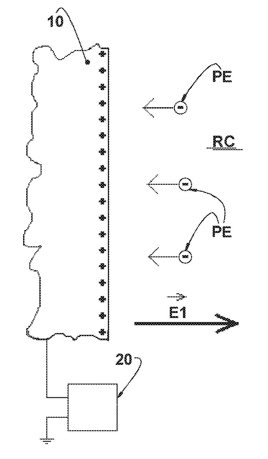
[0039]As already discussed previously, the present invention relates to a novel method for increasing the density of a plasma, generally, but not necessarily, formed within a normally grounded reaction chamber RC and in which a mass of ionized elements, with a region of luminescence and including neutral atoms NA of an ionizable fluid in the gas or liquid phase and primary electrons PE and positive ions PI formed in an initial phase or in a starting ionization phase of the ionizable fluid within the reaction chamber RC of a suitable reactor (not shown). It should be understood that the electrodes may or not be contained in a reaction chamber RC, and if contained, one of the electrodes may or may not be defined by the wall (not shown) of said reaction chamber RC.

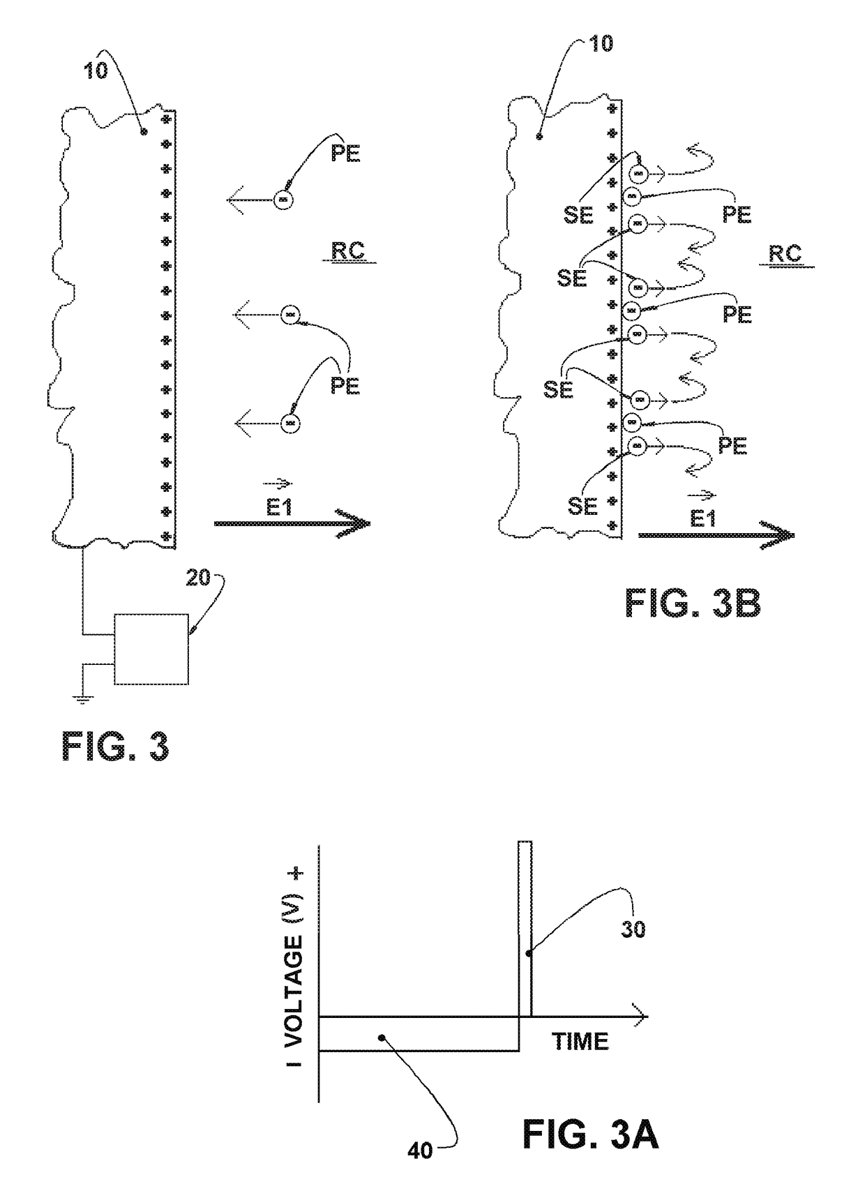
[0040]In brief, the method consists of controlling the waveform of the voltage applied to the electrodes and, consequently, controlling the energy and the intensity of secondary electrons SE, that will be described further. T...


PUM


Abstract

The plasma is formed between electrodes to be energized from an electric power source, containing a partially ionized mass having a luminescence region including neutral atoms (NA), primary electrons (PE), secondary electrons (SE), and ions.The method comprises the interspersed steps of: accelerating the primary electrons (PE) toward one of said electrodes (10) polarized by a short, positive, high voltage pulse, impacting primary electrons (PE) against said electrode (10) and ejecting secondary electrons (SE) from it; subsequently, accelerating the secondary electrons (SE) toward the luminescence region by polarization of said electrode (10) by a negative voltage with a lower voltage pulse colliding the secondary electrons with neutral atoms (NA) and producing positive ions (PI) and derived electrons (DE); the negative pulse must have a period of time sufficient to accelerate the positive ions (PI) of the luminescent region towards the electrodes 10, striking the surface of said electrodes; repeating the previous steps in order to obtain a steady state plasma with a desired degree of ionization. The control of the intensity and the period of the positive and negative pulses allow the control of the degree of ionization and the volume of the luminescent region of the plasma.

Description

CROSS-REFERENCE TO RELATED APPLICATIONS[0001]This Application claims priority for Application BR1020160067863 filed on Mar. 28, 2016 in Brazil.FIELD OF THE INVENTION[0002]This invention relates the generation and control of the physical state of plasma for different applications. More specifically, the invention describes a method for better controlling and amplifying the degree of ionization of the plasma formed within an electrical discharge chamber provided with two or more electrodes, where one of them may be the chamber wall. The method uses the control of electric voltage pulses for generating a gain in the emission of electrons from the electrodes.BACKGROUND OF THE INVENTION[0003]There are several ways to generate a plasma state, and they can be classified into two large areas: “Capacitively Coupled Plasma (CCPs)” and “Inductively Coupled Plasma (ICPs)”. The plasma sub-classifications depend on the waveforms of the applied voltage, among which can be listed the following: RF ...

Claims


Application Information

Patent Timeline
Patent Type & Authority Applications(United States)
IPC IPC(8): H05H1/46H01J37/32
CPCH05H1/46H05H1/24H01J37/32009H01J37/32091H01J37/32146H05H1/466H01J2237/0473H01J37/05
Inventor SCHOLTZ, JULIANO SADIFONTANA, LUIS CESAR
Owner SCHOLTZ E FONTANA CONSULTORIA LTDA ME
Why Eureka
Try Eureka