Optical Arrangement For Power-Efficient, Low Noise Photoplethysmographic Sensor Module

a sensor module and low noise technology, applied in the field of biometric monitoring devices, can solve the problems of inconvenient or uncomfortable wearing of chest straps, unique problems in rate measurement solutions, and limited heart rate measuremen

Inactive Publication Date: 2017-10-05
SILICON LAB INC
View PDF2 Cites 15 Cited by
  • Summary
  • Abstract
  • Description
  • Claims
  • Application Information

AI Technical Summary

Benefits of technology

[0017]In this embodiment, the photodetector is preferably arranged on the PPG sensor module between the first and second LEDs, such that a first distance separating the photodetector and the first LED is substantially greater than or substantially less than a second distance separating the photodetector and the second LED. For example, the first distance may be approximately 2 to approximately 16 times greater than or less than the second distance. By separating the first LED / photodetector pair and the second LED / photodetector pair by a substantially different distance, the improved PPG sensor module may provide signal diversity by providing different signal paths for the reflected light to return to the photodetector.

Problems solved by technology

Heart rate measurement has traditionally been limited to the use of chest straps linked to an external device, such as a smartphone or specialized fitness watches, or to electrical touch pads integrated onto fitness equipment.
These heart rate measurement solutions pose unique problems.
For example, many people find chest straps inconvenient or uncomfortable to wear, while others find smartphones difficult to monitor while running or cycling and fitness watches too bulky.
Since the electrical touch pads integrated onto fitness equipment are not wearable biometric monitoring devices, heart rate measurement can only be obtained from these devices while a user is in contact with the touch pads.
However, the measurement accuracy of conventional wrist-worn monitoring devices is often adversely affected by weaker blood flow signals in the wrist (compared to chest), complex motion artifacts introduced into the measurement signal by user motion, differences in skin composition and color, and / or poorly designed sensor modules.
Conventional wrist-worn monitoring devices also tend to be costly and power hungry, which limits the battery life of such devices.
Some wrist-worn biometric monitoring devices are also bulky and cumbersome to wear.

Method used


Image

  • Optical Arrangement For Power-Efficient, Low Noise Photoplethysmographic Sensor Module
  • Optical Arrangement For Power-Efficient, Low Noise Photoplethysmographic Sensor Module
  • Optical Arrangement For Power-Efficient, Low Noise Photoplethysmographic Sensor Module

Examples


Embodiment Construction

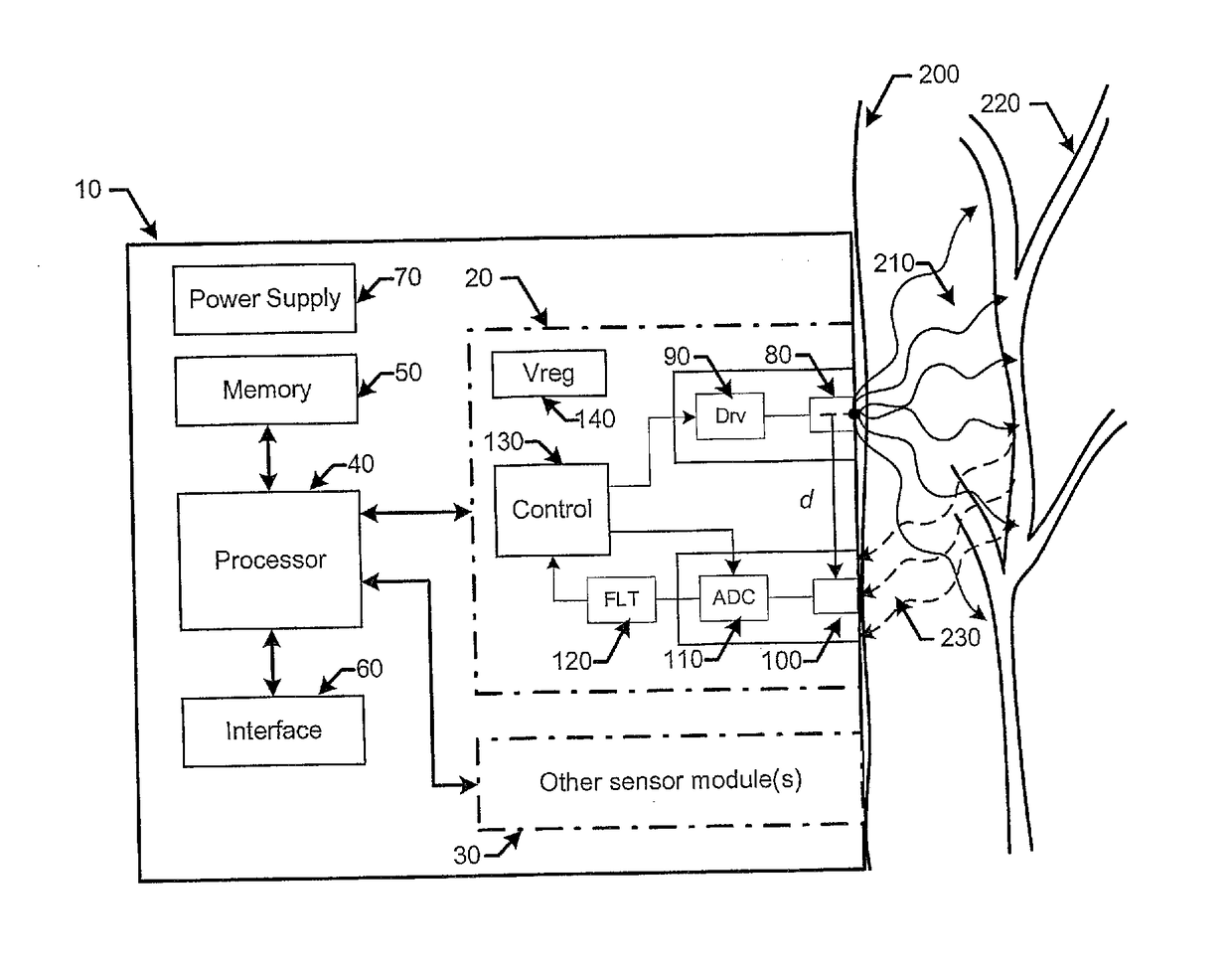
[0029]The present disclosure is directed to biometric monitoring devices, which are typically (although not exclusively) designed to be worn by a user continuously, intermittently or during certain activities (e.g., while exercising). Wearable biometric monitoring devices are usually small in size, so as to be relatively unobtrusive for the wearer, and are typically designed to be worn for long periods of time without discomfort. These devices may be worn on a variety of different body parts including, for example, a user's wrist, arm, ankle, leg or chest, without interfering with the user's range of motion or daily activities. As such, a wearable biometric monitoring device may be provided in a variety of form factors including various configurations of bands or straps, which are sized to accommodate a user's wrist, arm, ankle, leg or chest, and configured to compress the device against the user's skin. Alternatively, a wearable biometric monitoring device may be attached to a user...


PUM


Abstract

According to one embodiment, a power-efficient, low noise photoplethysmographic (PPG) sensor module is provided herein comprising at least one light emitting diode (LED) and at least one photodetector. The LED is generally configured for emitting light, and is positioned on the PPG sensor module for transmitting the emitted light into biological tissue. The photodetector is generally configured for detecting a portion of the light that is transmitted by the LED into the biological tissue and reflected back to the photodetector. The photodetector is an elongated photodetector having a longer dimension that is at least 1.5 times larger than a shorter dimension of the elongated photodetector. By positioning the elongated photodetector on the PPG sensor module, such that the longer dimension is facing towards the first LED, the elongated photodetector is configured to collect substantially more of the reflected light, thereby increasing the signal-to-noise ratio of the detected signal.

Description

BACKGROUND1. Field of the Disclosure[0001]This disclosure relates to biometric monitoring devices and, more particularly, to an optical arrangement for a power-efficient, low noise photoplethysmographic (PPG) sensor module included within a biometric monitoring device.2. Description of the Relevant Art[0002]The following descriptions and examples are provided as background only and are intended to reveal information that is believed to be of possible relevance to the present disclosure. No admission is necessarily intended, or should be construed, that any of the following information constitutes prior art impacting the patentable character of the subject matter claimed herein.[0003]Recent advances in sensor, electronics, and power source miniaturization have allowed the size of personal health monitoring devices, also referred to herein as biometric monitoring devices, to be offered in small sizes. These biometric monitoring devices may collect and / or derive one or more types of ph...

Claims


Application Information

Patent Timeline
Patent Type & Authority Applications(United States)
IPC IPC(8): A61B5/024A61B5/00A61B5/0205
CPCA61B5/02427A61B5/681A61B5/02055A61B5/02438A61B5/02007A61B5/0205A61B5/021A61B5/02433A61B5/14532A61B5/14552A61B5/6813A61B5/7203A61B2560/0209A61B2562/046A61B5/02444
Inventor ALTMEJD, MOSHE M.DEL SIGNORE, BRUCE P.ZHANG, YAHUI
Owner SILICON LAB INC
Why Eureka
Try Eureka