Processing of solid micron sized particles for rapid deposition on substrate surfaces with uniform particle distribution

a technology of solid micron particles and substrate surfaces, applied in the direction of chemistry apparatus and processes, instruments, grain treatment, etc., can solve the problems of difficult production of consistent standard materials, difficult trace residues, and largely limited control of inkjet process particle deposition, so as to accelerate the sieving process and achieve superior sieving performance , the effect of greater control over particle deposition

Active Publication Date: 2017-10-05
THE UNITED STATES OF AMERICA AS REPRESENTED BY THE SECRETARY OF THE NAVY
View PDF0 Cites 17 Cited by
  • Summary
  • Abstract
  • Description
  • Claims
  • Application Information

AI Technical Summary

Benefits of technology

[0013]In contrast to the existing techniques described in the prior art, in some aspects, the present invention beneficially accelerates the sieving process while providing greater control over particle deposition. In some aspects, a blade is provided that is in contact with a sieving membrane. In other aspects, the invention only loads the sieve with a small amount of material that barely covers the surface of the sieving membrane. Accordingly, the products, systems, and methods of the invention beneficial

Problems solved by technology

Such techniques are possible because the process of manufacturing threats, such as explosives, typically results in trace residues including particles of the threat material being left on persons and objects associated with manufacturing process.
Given the very small amounts and volatility of the materials involved, production of consistent standard materials is difficult.
Inkjetting is largely limited in its control of particle deposition by the solvent selected and its interaction or wetting with a surface.
None of these represent typical particles found in fingerprints because their sizes and groupings do not match what is produced in an actual fingerprint.
In addition, because drops deposited by inkjetting are typically very small, they evaporate very quickly and may trap substantial amounts of solvent in the produced crystal.
The sieving stacks are typically operated in ambient air, which limits their practical use to particles of about 20 microns and above.
Using the conventional sieving stacks, the sieving of particl

Method used


Image

  • Processing of solid micron sized particles for rapid deposition on substrate surfaces with uniform particle distribution
  • Processing of solid micron sized particles for rapid deposition on substrate surfaces with uniform particle distribution
  • Processing of solid micron sized particles for rapid deposition on substrate surfaces with uniform particle distribution

Examples


example 1

[0181]In order to test a sieving assembly incorporating a wiper blade therein, a sieving apparatus was fitted with a wiper blade that revolved at 50 rpm. The rotating coupon holder was fitted with four 1×41 1″ square glass coupons, and a mask having four 0.8″×0.8″ square openings was applied over the coupon holder and coupons.

[0182]A sieve with 20 micron openings and containing a prefractionated load of from 0 to 38 microns was used, and sieving was carried out for 3 minutes to a coupon load of 30 micrograms / cm2. Wiper blade sieving results in 10-20 times greater particle throughput as compared to sieves not incorporating a blade that contacts the sieving membrane, and prevents or reduces particle pooling. Use of the rotating coupon platform further evens out particle distribution. The vibration isolation provided by the rubber feet between the base of the rotating coupon platform and the collection pan limits particle redistribution after deposition on the coupons.

[0183]No vibrator...

example 2

[0184]In one implementation of the mechanical decoupling technique, custom cylindrical-shaped rubber feet were fabricated. The feet were designed to friction fit into 4 matching notches machined in the bottom side of the coupon holder and to protrude to lift the coupon holder away from the floor of the collection pan and enable the coupon holder to oscillate horizontally (shear mode). The friction fit design allows for easy cleaning and replacement for applications operating in a different frequency domain. It was found that the four feet provide suitable stability for the coupon holder while the vibration sieving operation was carried out.

[0185]The polymers considered for fabricating the feet were based on products from Smooth-On, Inc., of Macungie, Pennsylvania. In this comparative analysis, the Smooth-On, Inc. products Ecoflex® 00-30 and Dragon Skin 20 were compared. Ecoflex® 00-30 has a Shore hardness of 30 based on the Shore 00 scale. This hardness is comparable to the hardness...

example 3

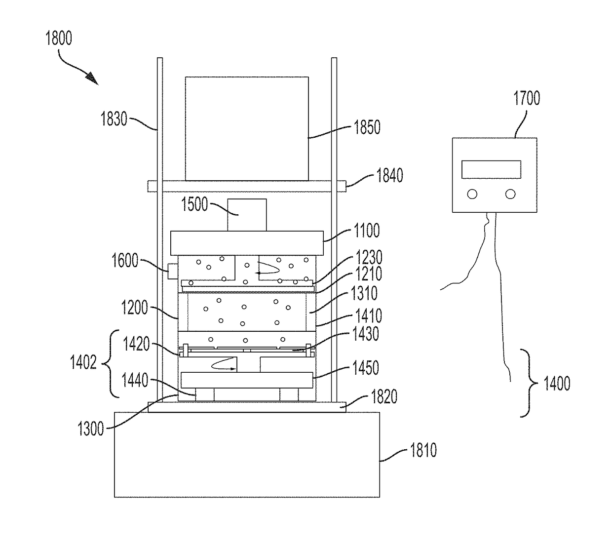
[0192]The dust storm deposition technique is illustrated in FIG. 14. The system consists of a cylindrical container, an electrical fan (with power supply and controller), an appropriate substrate holder and the particles to be deposited on the substrate or coupon(s). The fan establishes a cyclonic airflow within the container which drives micron sized particles in a circular motion, and then lifts them up towards the top of the container where the particles adhere to one or more coupons.

[0193]The glass jar selected in the preliminary experiment described here was selected for convenience and to allow easy visual observations. The fan selected was a simple vane axial fan. The direction of the air flow was directed downwards towards the bottom of the glass jar. The rotational direction of the fan can be ignored. The two wires for power supply plus an additional wire without functionality held the fan in position. The lid of the jar contains a simple substrate holder which allows easy ...


PUM


Abstract

This application relates generally to a method and apparatus to deposit particles onto one or more coupons, and harvest particles from one or more coupons, which may beneficially provide a more uniform or localized distribution of particles over a specified area on each coupon. The application relates to a method and apparatus for depositing particles onto one or more coupons using a sieve. The application also relates to a method and apparatus for depositing particles onto one or more coupons using a dust storm. The particle loadings achieved on each coupon or across an individual coupon may be substantially uniform. The application further relates to a laser-based method and apparatus for transferring particles deposited at localized points on a source coupon to a different substrate for further use.

Description

CROSS-REFERENCE TO RELATED APPLICATIONS[0001]This application claims the benefit of priority under 35 U.S.C. §119(e) from U.S. Provisional Application No. 62 / 318,651, filed on Apr. 5, 2016, the contents of which are incorporated herein by reference in their entirety.TECHNICAL FIELD[0002]This application relates generally to a method and apparatus to deposit particles onto one or more coupons, and harvest particles from one or more coupons, which may beneficially provide a more uniform or localized distribution of particles over a specified area on each coupon. The application relates to a method and apparatus for depositing particles onto one or more coupons using a sieve. The application also relates to a method and apparatus for depositing particles onto one or more coupons using a dust storm. The particle loadings achieved on each coupon or across an individual coupon may be substantially uniform. The application further relates to a laser-based method and apparatus for transferr...

Claims


Application Information

Patent Timeline
IPC IPC(8): G01N21/01G01N1/28B02C17/18
CPCG01N21/01G01N1/286B02C17/184B07B1/52B07B1/522B07B1/524B07B1/526B07B1/528B07B13/16G01N2015/1018G01N1/28G01N2001/2893G01N15/10
Inventor FURSTENBERG, ROBERTFISCHERNGUYEN, VIET K.MCGILL, R ANDREWKENDZIORA, CHRISPAPANTONAKIS, MICHAEL
Owner THE UNITED STATES OF AMERICA AS REPRESENTED BY THE SECRETARY OF THE NAVY
Why Eureka
Try Eureka