
Nvb trickle-charger system with built-in auto-dummy-load using si-mos-sub-vth micro-power pyroelectricity

a micro-power pyroelectricity and trickle-charger technology, applied in the direction of generators/motors, transportation and packaging, apparatus without intermediate ac conversion, etc., can solve the problems of variable battery efficiency, inability to reliably recharge disposable primary cells, and inability to meet high-drain applications with loads, etc., to achieve the effect of boosting pyroelectricity

Inactive Publication Date: 2017-10-05
BOARD OF RGT THE UNIV OF TEXAS SYST
View PDF0 Cites 0 Cited by
  • Summary
  • Abstract
  • Description
  • Claims
  • Application Information

AI Technical Summary

Benefits of technology

The patent describes a circuit that can boost the voltage of pyroelectricity to charge batteries. The circuit has a controlled ripple DC signal that reduces peak voltage and prevents over-charging. The circuit also uses dual current paths and a single rail system to cascade the step-up voltage. The circuit helps to trickle charge devices while ensuring optimal performance.

Problems solved by technology

Disposable primary cells cannot be reliably recharged, since the chemical reactions are not easily reversible and active materials may not return to their original forms.
In general, these have higher energy densities than rechargeable batteries, but disposable batteries do not fare well under high-drain applications with loads.
Internal energy losses and limitations on the rate that ions pass through the electrolyte cause battery efficiency to vary.
The complexity (and cost) of the charging system is primarily dependent on the type of battery and the recharge time.
All of the gas formed must be able to recombine internally, or pressure will build up within the cell eventually leading to gas release through opening of the internal vent which reduces the life of the cell.
The big disadvantage of slow charge is that it takes a long time to recharge the battery, which is a negative marketing feature for a consumer product.
Fast charging at lower temperatures (10-20° C.) must be done very carefully, as the pressure within a cold cell will rise more quickly during charging, which can cause the cell to release gas through the cell's internal pressure vent (which shortens the life of the battery).
This results in a very sharp increase in both cell temperature and internal pressure if high current charging is continued.
The cell contains a pressure-activated vent which should open if the pressure gets too great, allowing the release of gas (this is detrimental to the cell, as the gas that is lost can never be replaced).
A severely overcharged cell can explode if the vent fails to open due to deterioration with age or corrosion from chemical leakage.
At the higher the temperature, the greater the corrosion rate and the sooner the failure of the battery.
This accelerated corrosion at higher temperatures occurs regardless of the charge current flowing into the battery.
However, since higher temperatures give rise to increased currents at a given voltage setting, the net result of an elevated battery ambient temperature is to intensify the negative effects on the battery.
In an ideal battery, the terminal voltage would be constant over the whole discharge time, until when the battery is finally fully discharged, the voltage would drop right down (although this could make battery level detection quite hard).
However, the battery itself provides the smoothing in this scheme, and regulation is unnecessary.

Method used


Image

  • Nvb trickle-charger system with built-in auto-dummy-load using si-mos-sub-vth micro-power pyroelectricity
  • Nvb trickle-charger system with built-in auto-dummy-load using si-mos-sub-vth micro-power pyroelectricity
  • Nvb trickle-charger system with built-in auto-dummy-load using si-mos-sub-vth micro-power pyroelectricity

Examples


Embodiment Construction

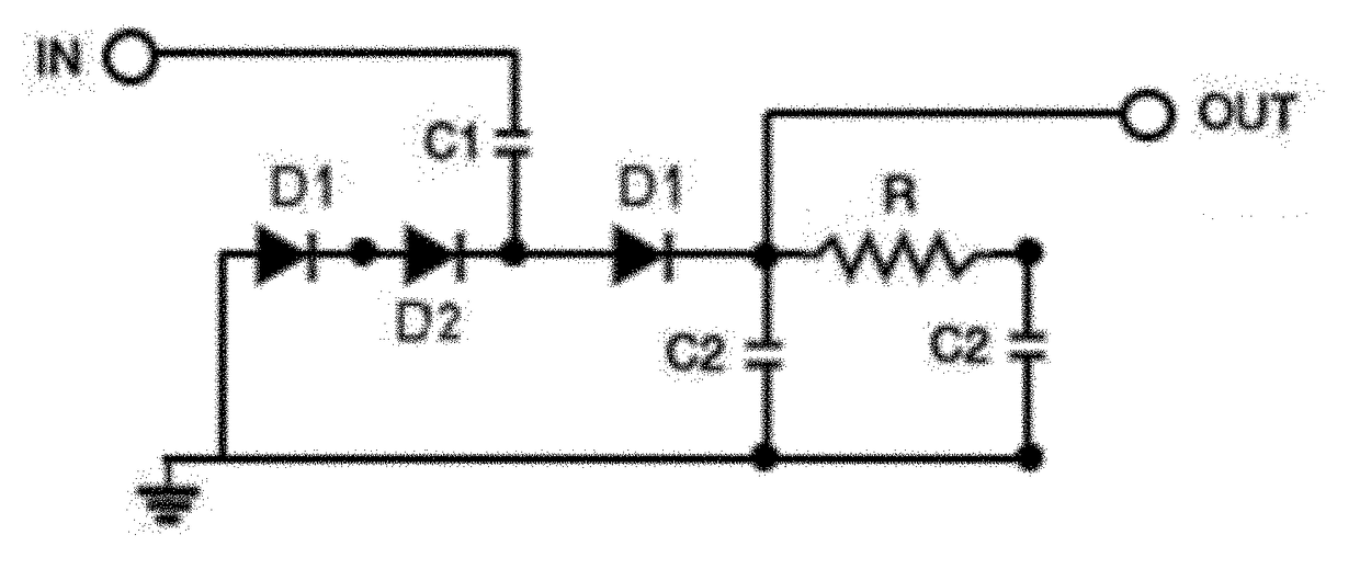
[0046]Disclosed herein is a novel Non-Inductive Voltage Boost (NVB) Trickle Charger (NVB-TC) System with Built-In Auto-Dummy-Load (ADL).

[0047]From the previous discussion we know that battery's charging-discharging system and slow charging and fast charging methods and so on. Presented now is the trickle charging operation.

[0048]Trickle Charging Operation of NVB Converter

[0049]Trickle chargers are commonly used to charge batteries of low capacity. This means that it tends to be slower when providing energy to batteries. Because it does not support speedy charging, this kind of chargers can also be used as a maintainer. If the batteries are connected to the chargers for quite a long time, the batteries will not be overheating or getting damaged. So the advantages of trickle charging are:

1. Extends the life of a battery

2. Trickle charges prevent batteries from becoming sulfated

3. No longer need to replace batteries frequently when these trickle chargers are used.

[0050]Performance

[0051...


PUM


Abstract

Disclosed herein is a device, system, and method for a trickle charging system of non-inductive voltage boost (NVB) converter with built-in auto-dummy-load (ADL) for wide-range of charge storage devices i.e. small button-cell type batteries and super-caps using micro power pyro-electricity at Si-MOS sub-threshold voltage. A VLSI configuration of the system is also disclosed in embodiments. The system converts the pyro-electric material at MOS sub-threshold 0.37V for optimizing to the battery charging level at 1.45V. This system was proven at hardware level and found to be 98.8% power efficient. The designed IC can charge independently without any external components for up to 1 uW max, but able to charge up to 20 uA with external components. Thus it is considered to be a very versatile design.

Description

CROSS-REFERENCE TO RELATED APPLICATIONS[0001]This application claims priority to, and is the National Stage of International Application No. PCT / US15 / 47063 filed on Aug. 26, 2015 and claims priority of U.S. Provisional Patent Application Ser. No. 62 / 042,212, filed on Aug. 26, 2014, the contents of which are incorporated by reference in their entirety.STATEMENT REGARDING FEDERALLY SPONSORED RESEARCH OR DEVELOPMENT[0002]This invention was made with government support under grant no. 1002380 and grant no. 0844081 awarded by the National Science Foundation. The government has certain rights in the invention.FIELD OF THE INVENTION[0003]The present invention generally relates to a device, system and method for trickle charging.BACKGROUND OF THE INVENTION[0004]Batteries provide electrical energy through an electro-chemical process. Batteries are made-up of one or more cells in series or parallel combinations to increase voltage and output capacity.[0005]The electro-chemical cells consists ...

Claims


Application Information

Patent Timeline
IPC IPC(8): H02J7/00H02M1/14H02N10/00H02J7/34
CPCH02J7/0065H02N10/00H02M1/14H02J7/34H02M3/06H02M3/08H02J2207/20H02M7/05
Inventor BINZAID, SHUZABHALLA, AMAR S.GUO, RYANHASAN, MD QUMRUL
Owner BOARD OF RGT THE UNIV OF TEXAS SYST
Learn More