
Battery-system-deterioration control device, and method thereof

a control device and battery system technology, applied in adaptive control, secondary cell servicing/maintenance, instruments, etc., can solve problems such as deterioration control devices, and achieve the effects of reducing the amount of data, reducing the effect of deterioration state variability, and highly precise deterioration models

Inactive Publication Date: 2017-10-12
KK TOSHIBA
View PDF4 Cites 13 Cited by
  • Summary
  • Abstract
  • Description
  • Claims
  • Application Information

AI Technical Summary

Benefits of technology

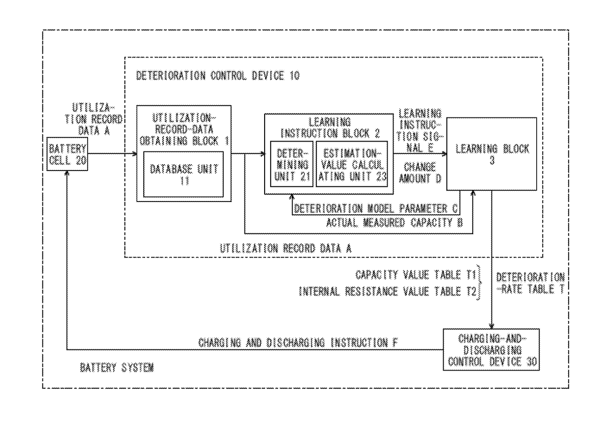
The patent text addresses the technical problem of creating a deterioration control device for a battery system that can eliminate the effect of variability in the deterioration state of each battery cell and construct a highly precise deterioration model, even if data obtained from the entire battery system is utilized. The device should be compatible to the diversification of an application, reduce the amount of data needed for deterioration control, and be able to handle the unstable data output from the battery system.

Problems solved by technology

Charging-and-discharging control devices create a charging and discharging schedule, and the utilization pattern of the batteries based on the obtained estimation result from deterioration control devices.
This includes a technical problem like the sensor accuracy, etc., for measuring the utilization record data, and a deterioration evaluation under an actual utilization condition is desired.

Method used


Image

  • Battery-system-deterioration control device, and method thereof
  • Battery-system-deterioration control device, and method thereof
  • Battery-system-deterioration control device, and method thereof

Examples


first embodiment

(3) First Embodiment

[0076][Structure]

[0077]According to a first embodiment, the learning block 3 among the three blocks in the deterioration control device 10 has characteristic structures. As illustrated in FIG. 3, the learning block 3 includes a current integrating unit 31, a constant-current-capacity detecting unit 32, a constant-voltage-capacity detecting unit 33, and a deterioration-rate-table learning unit 34. Among those units, the current integrating unit 31 calculates the actual measured capacity B in accordance with the utilization record data A from the utilization-record-data obtaining block 1 and detection signals G1, G2 from the detecting units 32, 33, and outputs the actual measured capacity B to the learning instruction block 2.

[0078]By combining the current integrating unit 31 and the constant-current-capacity detecting unit 32, a capacity at a constant current is calculated, and by combining the current integrating unit 31 and the constant-voltage-capacity detectin...

second embodiment

(4) Second Embodiment

[0110][Structure]

[0111]According to a second embodiment, the learning block 3 has characteristic features, like the first embodiment, and the basic structure is the same as that of the first embodiment. Hence, the same structural component as that of the first embodiment will be denoted by the same reference numeral, and the explanation thereof will be omitted. The learning block 3 in the first embodiment has all structural components provided at the local side.

[0112]On the other hand, according to the second embodiment, although the learning block 3 employs the same structure, the location where the structural components are provided is divided into the local side of the battery system and the server side thereof. FIG. 9 illustrates such structure according to the second embodiment. As illustrated in FIG. 9, the learning block in the second embodiment is divided into a learning block 3A at the local side, and a learning block 3B at the server side.

[0113]The lea...

third embodiment

(5) Third Embodiment

[0121]Following third to sixth embodiments have characteristic features in the structure of the utilization-record-data obtaining block 1. The utilization-record-data obtaining block 1 is one of the three blocks which are roughly divided in the deterioration control device 10. In the third to sixth embodiments, the structures other than the utilization-record-data obtaining block 1 is the same as those of the first embodiment, and the explanation thereof will be omitted.

[0122][Structure]

[0123]As illustrated in FIG. 11, the utilization-record-data obtaining block 1 according to the third embodiment includes, in addition to the database unit 11 explained in the paragraph [0029], a characteristic parameter detecting unit 12. The characteristic parameter detecting unit 12 is connected to a first simulation unit 14A and an encoding unit 15, and the first simulation unit 14A is connected to a difference detecting unit 13.

[0124]The difference detecting unit 13 is connec...


PUM


Abstract

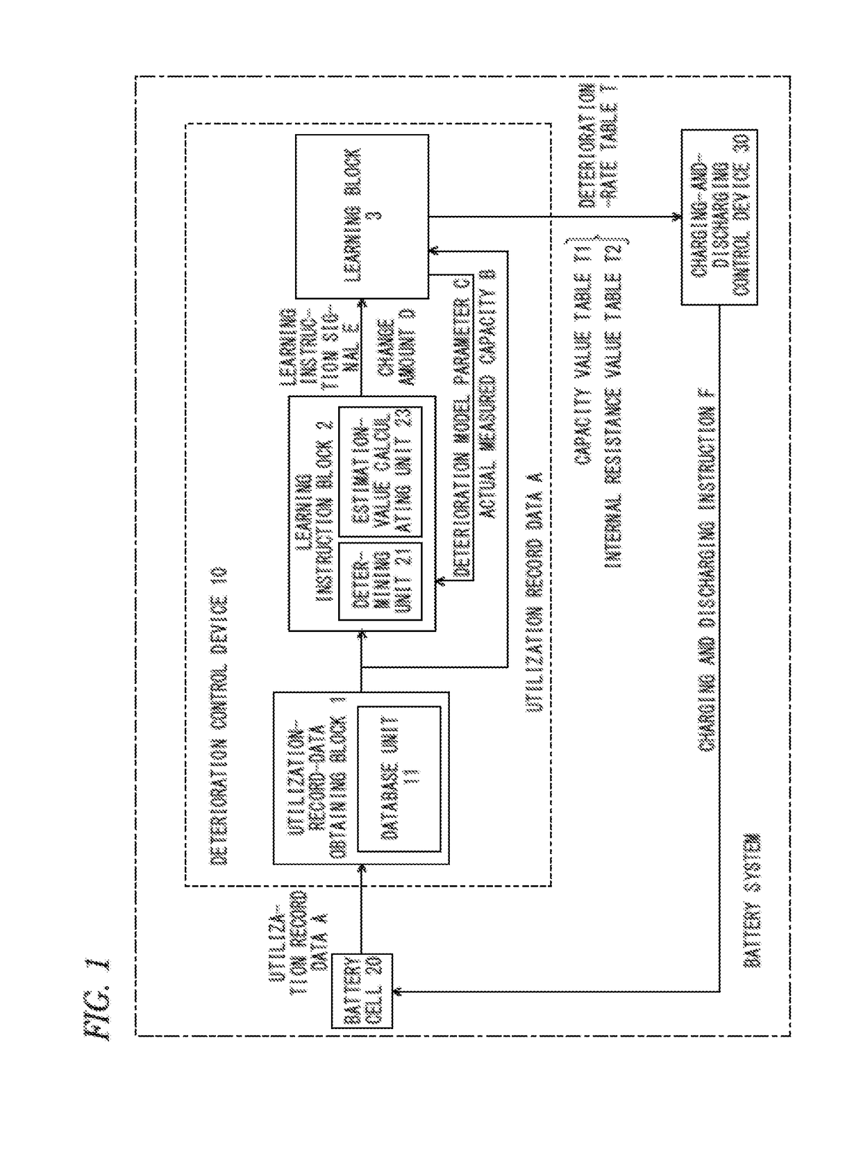
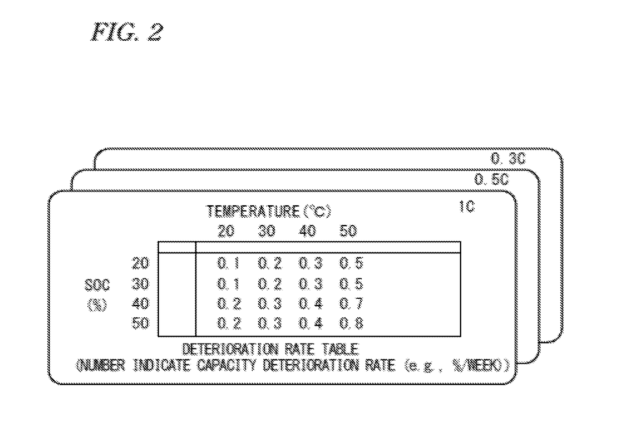
A battery-system deterioration control device compatible to diversification of applications by appropriately learning a necessary deterioration model for a deterioration control. The battery-system deterioration control device includes a utilization-record-data obtaining block, a learning instruction block, and a learning block. The utilization-record-data obtaining block obtains utilization record data of a battery cell. The learning block updates a data amount of a deterioration model parameter indicating the deterioration state of the battery cell based on the utilization record data, learns the deterioration model parameter, and outputs the learnt result that is a deterioration rate table. The learning instruction block compares the utilization record data and the data amount that is the estimation value, determines the necessity of learning of the deterioration model parameter, and outputs a learning instruction signal to the learning unit.

Description

TECHNICAL FIELD[0001]Embodiments of the present disclosure relate to a deterioration control device of a battery system and a method thereof.BACKGROUND ART[0002]In battery systems that have a large number of battery cells, actual measured values of the battery cell, such as the voltage value, the temperature value, and the SOC (remaining battery level) value, are monitored to control the system. Exemplary control devices incorporated in the battery system are a deterioration control device and a charging-and-discharging control device. The deterioration control device has an important role such as estimating the deterioration state of the system based on the actual measured values.[0003]Data of the actual measured values of the battery cell is normally handled as utilization record data, and stored in a memory to construct a database. According to deterioration control devices for the battery system, an amount of data of a deterioration model parameter is calculated from the utiliza...

Claims


Application Information

Patent Timeline
IPC IPC(8): H01M10/44G05B13/02H01M10/48G01R31/36
CPCH01M10/441G01R31/3606G01R31/3679H01M10/486G05B13/0265G06N3/00H01M10/44H01M10/48H01M10/4285H03M7/30G01R31/367G01R31/396G05B13/04G01R31/392H02J7/0069Y02E60/10H02J7/005H02J7/0049G01R31/382
Inventor WADA, TAKAHISAKUBOTA, KAZUTOMIZUTANI, MAMIKUBOTA, MASAYUKI
Owner KK TOSHIBA
Learn More