Multilayer element including base multilayer body, magnetic sensor and microwave assisted magnetic head

Active Publication Date: 2017-10-26
TDK CORPARATION
View PDF7 Cites 31 Cited by
  • Summary
  • Abstract
  • Description
  • Claims
  • Application Information

AI Technical Summary

Benefits of technology

[0056]As shown in FIG. 2, a magnetoresistive effect element (MR element) 20 includes the base multilayer body 11, a free layer 21 where a direction of its magnetization varies according to an external magnetic field, a nonmagnetic spacer layer 22, a reference layer 23 and a pinned layer 24 where directions of their magnetization are pinned, and a cap layer 25 made from Ru or the like with a film thickness of approximately 0.4 nm to 20 nm, is a multilayer element where the free layer 21, the nonmagnetic spacer layer 22, the reference layer 23, the pinned layer 24 and the cap layer 25 are laminated on the buffer layer 11B of the base multilayer body 11 in respective order, and has a current perpendicular-to-plane (CPP) structure in which a sense current is applied in the lamination direction.
[0057]The base multilayer body 11 in the magnetoresistive effect element (MR element) 20 has the same configuration as the base multilayer body 11 in the STO 10 (see FIG. 1).
[0058]As a material configuring the free layer 21, soft magnetic materials, such as CoFe, NiFe, CoFeB, CoFeSiB, CoFeHf, CoFeAl or CoFeTaB, and Co-based heusler alloys, such as Co2FeSi or Co2MnSi, can be exemplified, and the free layer 21 has a single layer structure or a lamination structure made from these materials. As a material configuring the reference layer 23, soft magnetic materials, such as CoFe or CoFeB, and Co-based heusler alloys, such as Co2FeSi or Co2MnSi, can be exemplified, and the reference layer 23 has a single layer structure or a lamination structure made from these materials. As a material configuring the pinned layer 24, CoFe, CoFeB, IrMn and the like can be exemplified, an

Problems solved by technology

However, if size of the magnetic grains is reduced, the problem where the thermal stability of magnetization of the magnetic grains is reduced in association with the reduction of the volume of the magnetic grains.
Consequently, if the magnetic anisotropy field of the magnetic recording medium exceeds the tolerance value determined from the upper limit of the recording field intensity, it is impossible to record onto a magnetic recording medium.
However, the perpendicular magnetic anisotropy of the SIL made from the [CoFe/Ni]n multilayered film is easily influenced by the crystal orie

Method used


Image

  • Multilayer element including base multilayer body, magnetic sensor and microwave assisted magnetic head
  • Multilayer element including base multilayer body, magnetic sensor and microwave assisted magnetic head
  • Multilayer element including base multilayer body, magnetic sensor and microwave assisted magnetic head

Examples


Example

Example 1

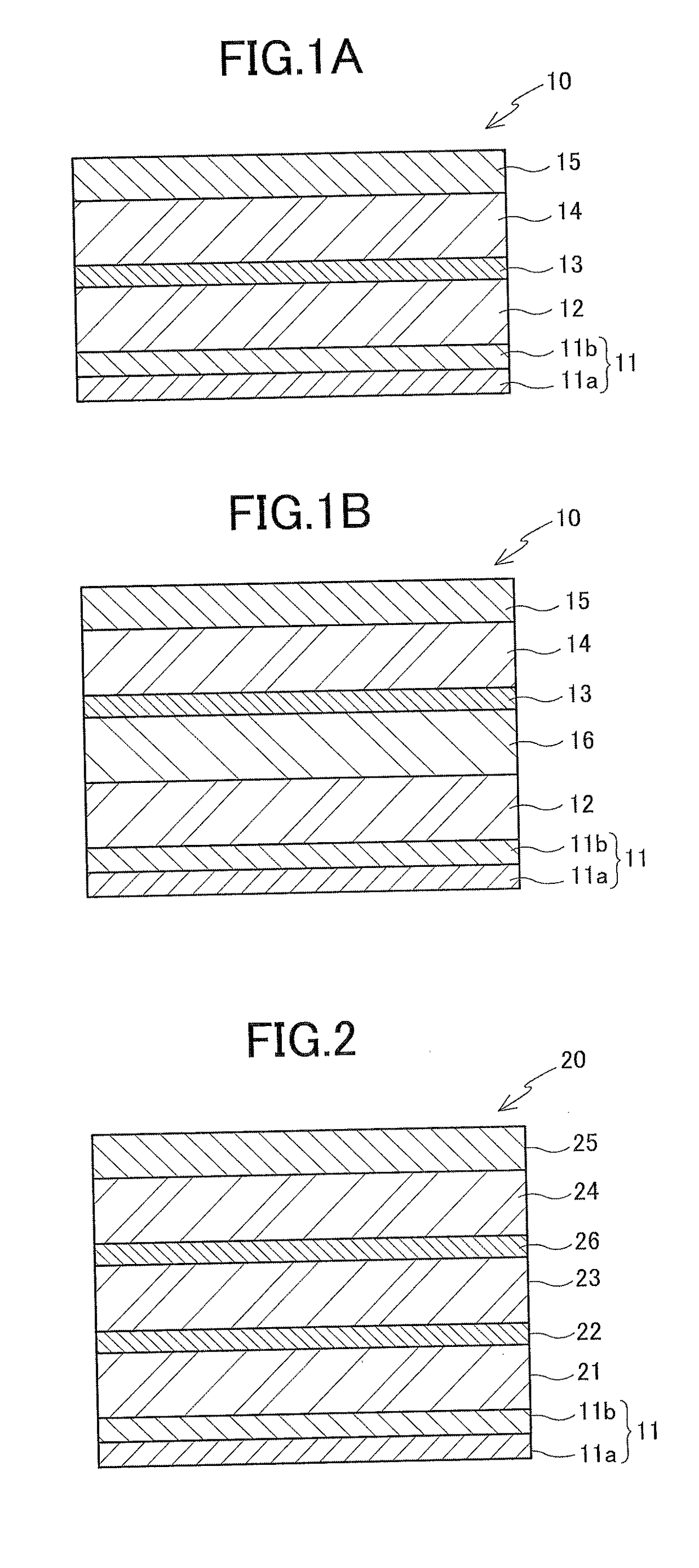
[0104]After a TaFe alloy layer (Ta: Fe=27 (at %): 73 (at %)) with a film thickness of 10 Å was formed as a seed layer on a silicon wafer using a sputtering method, an IrCr alloy layer with a film thickness of 20 Å was formed as a buffer layer using the sputtering method; thereby, a base multilayer body (total film thickness: 30 Å) was produced. [CoFe / Ni]20 was formed as a spin injection layer (SIL) on the buffer layer of the base multilayer body using the sputtering method, and a multilayer Le1 was produced.

Example

Example 2

[0105]The base multilayer body was produced in a manner similar to Example 1 except that the TaCo alloy layer (Ta: Co=27 (at %): 73 (at %)) with a film thickness of 10 Å was formed as a seed layer, [CoFe / Ni]20 was formed on the buffer layer of the base multilayer body as the SIL using the sputtering method, and a multilayer Le2 was produced.

Example

Example 3

[0106]The base multilayer body was produced in a manner similar to Example 1 except that the TaNi alloy layer (Ta: Ni=27 (at %): 73 (at %)) was formed, [CoFe / Ni]20 was formed on the buffer layer of the base multilayer body as the SIL using the sputtering method, and a multilayer Le3 was produced.


PUM


Abstract

A base multilayer body is made by laminating a seed layer and a buffer layer in respective order. The seed layer is an alloy layer containing tantalum (Ta) and at least one type of other metal, and having an amorphous structure or a microcrystal structure. The buffer layer is an alloy layer having a [001] plane orientation hexagonal close-packed structure and containing at least one type of a group VI metal and at least one type of a group IX metal in the periodic table. With this configuration, a magnetic layer providing a desired magnetic characteristic(s) can be laminated on the thinned base multilayer body.

Description

FIELD OF THE INVENTION[0001]The present invention relates to a base multilayer body and a multilayer element including the base multilayer body, a magnetic sensor and a microwave assisted magnetic head.BACKGROUND OF THE INVENTION[0002]In the field of magnetic recording using heads and media, there is demand for further improvement in the performance of magnetic recording media and magnetic heads in association with the high recording density of a magnetic disk device.[0003]The magnetic recording medium is a discontinuous medium where magnetic grains aggregate, and where each magnetic grain has a single magnetic domain structure. In the magnetic recording medium, one recording bit is configured of a plurality of magnetic grains. Consequently, in order to enhance the recording density, unevenness at the boundary of adjacent recording bits must be diminished by reducing the size of the magnetic grains. However, if size of the magnetic grains is reduced, the problem where the thermal st...

Claims


Application Information

Patent Timeline
IPC IPC(8): G11B5/39
CPCG11B5/3912G11B5/1278G11B5/235G11B5/3133G11B5/314G11B5/3146G11B2005/0024
Inventor TAKAHASHI, HIROKAZUROPPONGI, TETSUYASOENO, YOSHIKAZU
Owner TDK CORPARATION
Why Eureka
Try Eureka