
Fluid connection system and production method

a technology of flue gas connection system and production method, which is applied in the direction of pipe connectors, medical devices, pipe elements, etc., can solve the problems of not keeping a constant tightening torque throughout the life of the product, affecting the quality of the product, so as to reduce the risk of protruding areas causing perforation damage to the pouch, reduce the risk of contamination, and improve the effect of productivity

Active Publication Date: 2017-11-02
SARTORIUS STEDIM FMT SAS
View PDF16 Cites 7 Cited by
  • Summary
  • Abstract
  • Description
  • Claims
  • Application Information

AI Technical Summary

Benefits of technology

This patent describes a connection system for joining hose and connectors without using adhesive, which reduces the risk of contamination. The tightening of the hose and connector onto each other compensates for manufacturing tolerances, improving the seal and mechanical strength. A sleeve eliminates the risk of separation between the connector and hose, reducing the likelihood of leaks. The sleeve also prevents swelling of the flexible hose near the assembly region and protects against contamination. No cutting of the hose clamp is required, reducing particulate contamination and preventing damage to pouches. The sleeve can be carried out with an automated machine, improving productivity.

Problems solved by technology

However, placement of the clamp requires mechanically clamping it on the hose and cutting off its end, which runs the risk of particulate contamination.
In addition, there is the problem of tightening all clamps with uniform clamping forces from clamp to damp, due to The difficulty of automating this process.
The use of such clamps also poses problems in keeping a constant tightening torque throughout the life of the product (difficult because of creep over time in the plastic material of the elements of the fluid connection system).
Finally, the design of these clamps does not allow uniform clamping all along the periphery of the fluid connection.
This assembly method also adversely impacts clean room productivity since the hose clamp placement, tightening, and cutting are done manually and the total technical time required is particularly long.
In addition, certain constituent materials of the damp may be sources of contamination for the very clean environments (clean room, etc.) in which they are used.
And finally, despite precautions, a hose clamp could damage nearby flexible pouches or tubes with a potentially damaging part of said damp.
However, these connection systems have limited resistance to fluid pressure at the connection, and there is the issue of adapting the dimensions to the use.
The use of an adhesive may be unsuitable for the underlying material, and is temperature sensitive.
In addition, the use of an adhesive runs the risk of contaminating the biopharmaceutical fluid.
There is also the risk of deterioration of the components in contact with the adhesive, and migration into the biopharmaceutical fluid of contaminants originating from this deterioration.

Method used


Image

  • Fluid connection system and production method
  • Fluid connection system and production method
  • Fluid connection system and production method

Examples


Embodiment Construction

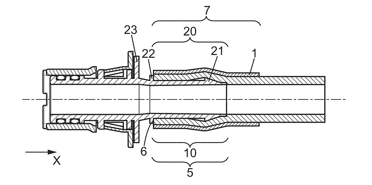
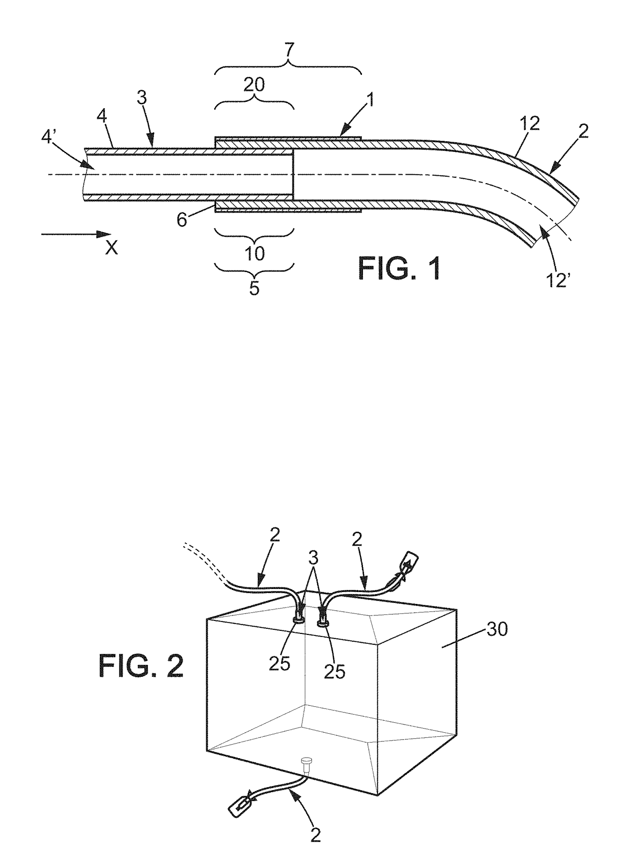
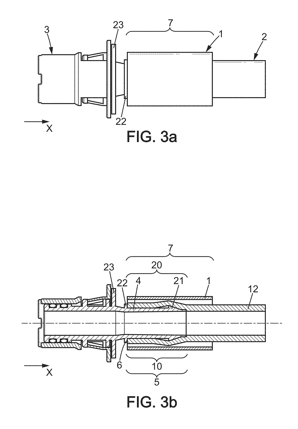
[0053]FIG. 1 shows a fluid connection system comprising a sleeve 1 that encloses the assembly between a hose 2 and a connector 3 (partially represented). The fluid connection system is intended for the transfer of biopharmaceutical fluid.

[0054]In the context of the invention, the term “biopharmaceutical fluid” is understood to mean a fluid derived from biotechnology—culture media, cell cultures, buffer solutions, artificial nutrition liquids, blood components and blood products derived therefrom, or a pharmaceutical fluid, or more generally a fluid for use in the medical field. Such fluids preferably have high purity requirements and must not be contaminated with foreign particles, whether these are particles from devices in contact with the fluids for their containment, transportation, or processing, or particles from the atmosphere surrounding these devices.

[0055]In the current example, in the final configuration of the system the sleeve 1 extends in the longitudinal direction X o...


PUM

PropertyMeasurementUnit
Temperatureaaaaaaaaaa
Timeaaaaaaaaaa
Forceaaaaaaaaaa

Abstract

Disclosed is a fluid connection system including a sleeve, a pipe and a fluid connector, the fluid connector including at least one rigid body made from a sterilizable biocompatible material, and the pipe including a flexible connection portion made from a sterilizable biocompatible material that is at least partially elastomeric. The fluid connector and the flexible connection portion of the pipe are assembled to one another, with the flexible connection portion of the pipe surrounding the rigid body, and the sleeve being shrunk tightly, but with free movement, on the pipe.

Description

FIELD OF THE INVENTION[0001]The present invention relates to fluid connection systems for the fluidtight transfer of medical and biopharmaceutical fluids, and to their manufacturing methods.BACKGROUND OF THE INVENTION[0002]There are already commonly known fluid connection systems for the fluidtight transfer of medical and biopharmaceutical fluids using a hose damp to retain a tube on a plastic endpiece, in patent application FR1356350. However, placement of the clamp requires mechanically clamping it on the hose and cutting off its end, which runs the risk of particulate contamination. In addition, there is the problem of tightening all clamps with uniform clamping forces from clamp to damp, due to The difficulty of automating this process. The use of such clamps also poses problems in keeping a constant tightening torque throughout the life of the product (difficult because of creep over time in the plastic material of the elements of the fluid connection system). Finally, the desi...

Claims


Application Information

Patent Timeline
IPC IPC(8): F16L47/22F16L33/30A61M39/10A61M39/12F16L33/207
CPCF16L47/22F16L33/2071F16L33/30A61M39/12A61M2207/00F16L2201/44A61M2205/0216A61M2039/1066A61M39/1011A61M39/00A61M39/10A61M39/16F16L33/22
Inventor BLAKE, FLORIANGAY, ISABELLE
Owner SARTORIUS STEDIM FMT SAS
Learn More