Compliant implantable connector and methods of use and manufacture

a technology of implantable connectors and connectors, which is applied in the direction of coupling contact members, coupling device connections, prostheses, etc., can solve the problems of corrosive fluid environment within the human body, general unsuitability of connectors for other implanted medical devices, and difficulty in implanting electrical connectors suitable for higher power requirements within the body. , to achieve the effect of maintaining integrity and longevity of electrical connectors and low yield strength

Active Publication Date: 2017-11-09
TC1 LLC
View PDF13 Cites 4 Cited by
  • Summary
  • Abstract
  • Description
  • Claims
  • Application Information

AI Technical Summary

Benefits of technology

[0012]In one aspect, the invention allows for an implantable connector having electrical contacts formed of materials with general material properties that are unsuitable for conventional connector geometries. As shown in the various embodiments described herein, the geometry of the urging member in conjunction with the interfacing contact surfaces allows the electrical contacts to be sufficiently engaged at a desired contact force (e.g., total axial contact force, localized contact force, radial compressive force) while stresses and strains within the contacts are maintained within a suitable range to avoid plastic deformation or fracture of the contact material, thereby maintaining integrity and longevity of the electrical connector. In some embodiments, the geometry of the connector is designed to keep localized forces within the contacts within an acceptable range for contact materials having low yield strength. In other embodiments, the geometry of the connector is designed to keep localized forces within the contacts within an acceptable range for contact materials that are brittle. It is appreciated that the size and shape of the interfacing contact surfaces affect the distribution of the reaction force, and in turn, the distribution of stress and strain within the material.

Problems solved by technology

Different types of device can have vastly different power requirements and use cases such that cables and associated connectors that are suitable for one type of device may not suitable for another type of device.
While these types of connectors have proven effective and dependable for many electrostimulation applications, these types of connectors may be generally unsuitable for other implanted medical devices such as those with relatively high power requirements (due to the high resistance associated with the canted coil spring design).
Since loss of power to an implanted VAD or failure to recharge an associated power supply poses life threatening consequences, to ensure continuous operation of the VAD, any connector used with an associated power cable or driveline cable must provide a dependable electrical connection for an extended period of time.
Implanting electrical connectors suitable for higher power requirements within the body can be challenging due to the cyclical stresses and strains attributed to flexure and movement of cords and devices within the body.
Another challenge with an implanted connector is that the fluid-filled environment within the human body can be corrosive to connector materials conventionally used in high-powered connectors, such as stainless steel and copper.
While certain non-corrosive alloys, such as a platinum iridium alloy (Pt—Ir), can be used, this material is exceedingly expensive and has mechanical properties that make its use in an implantable connector challenging (e.g., brittleness).
Given the design challenges associated with implantable device, however, many of these are overly bulky and expensive.

Method used


Image

  • Compliant implantable connector and methods of use and manufacture
  • Compliant implantable connector and methods of use and manufacture
  • Compliant implantable connector and methods of use and manufacture

Examples


Embodiment Construction

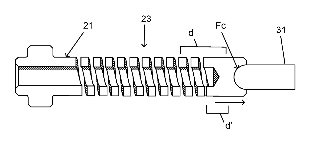
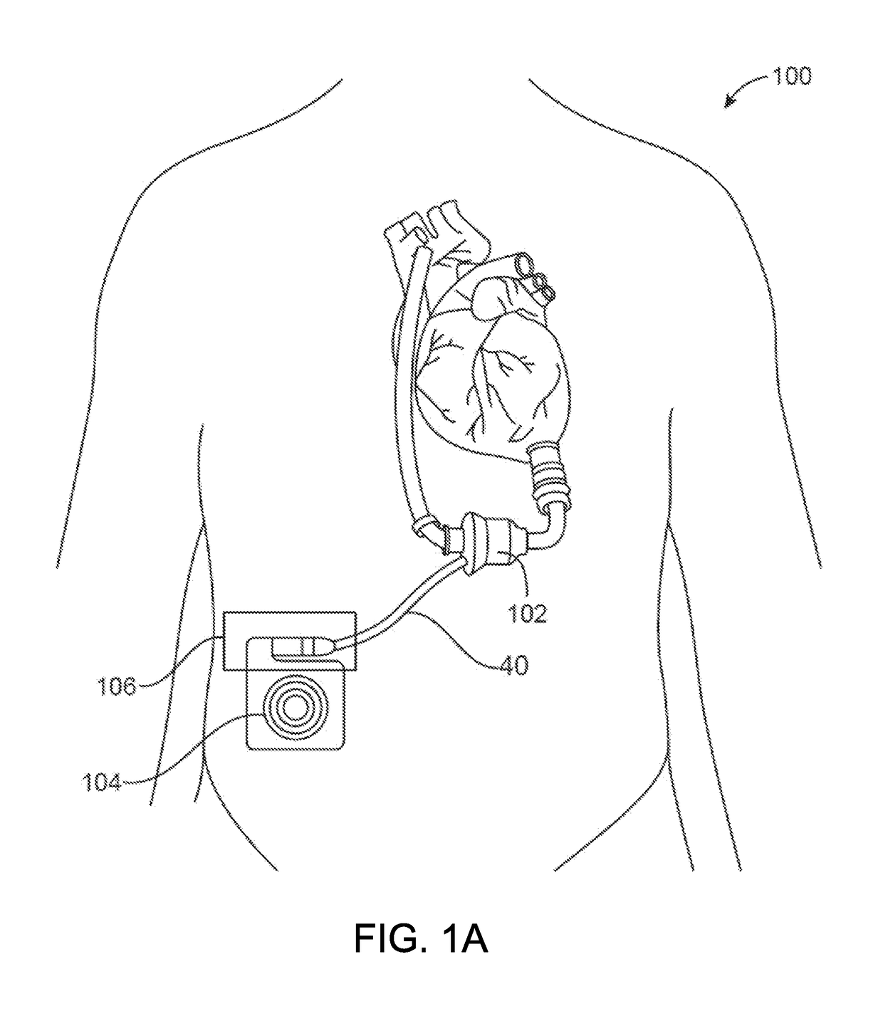
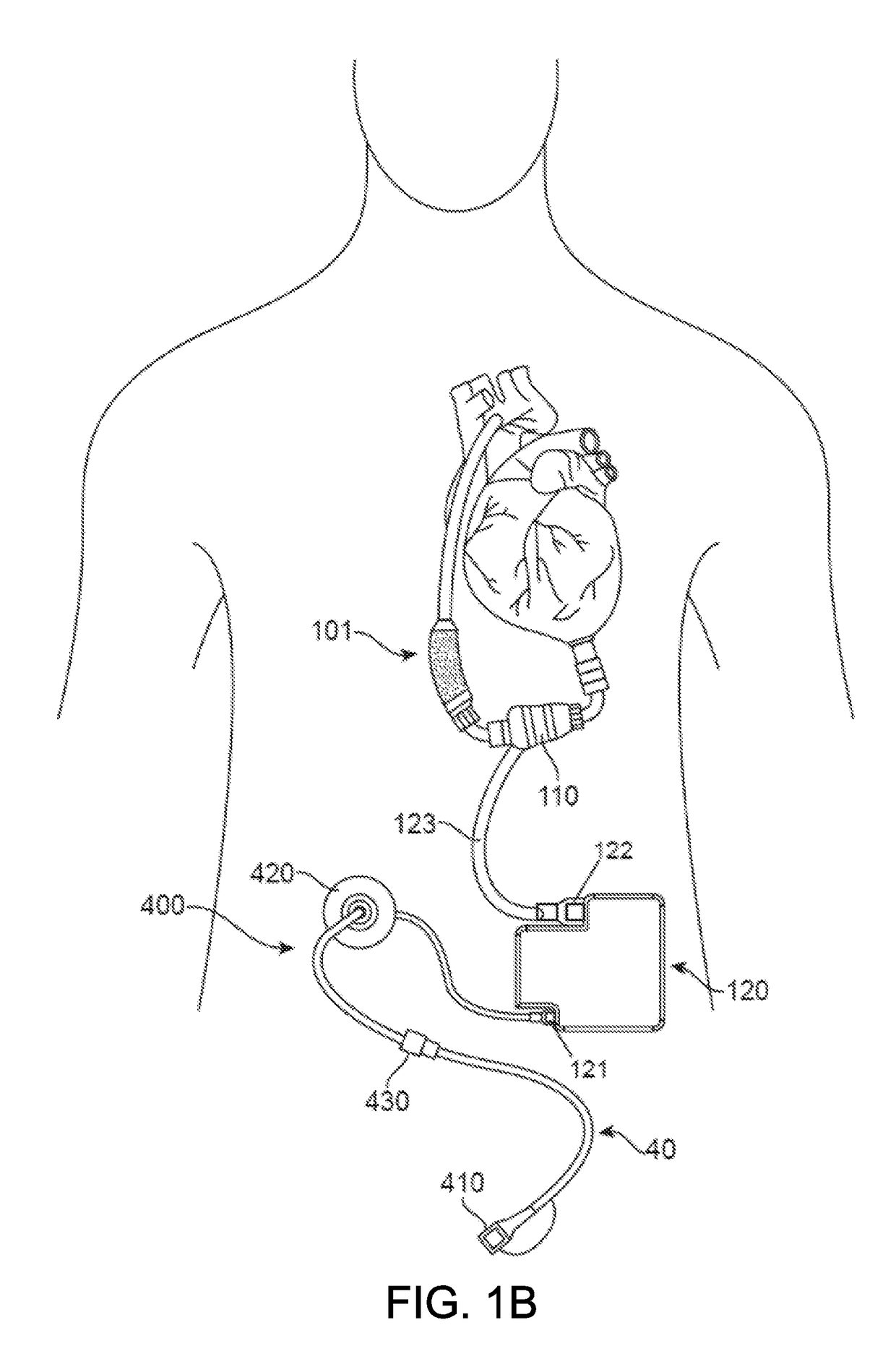
[0026]The invention relates generally to electrical connectors, and in particular to implantable connectors for use with power cables for powering high-powered implanted medical devices, such as a mechanical circulatory support system or VADs.

[0027]Developing connectors that are implanted in the human body is challenging, particularly for connectors that are designed to be connected and disconnected in a biological environment. The electrical contact set lies at the heart of any connector design. Current research and testing has demonstrated that electrical contacts that are subjected to a biologic environment are susceptible to corrosion—the biggest risk for implantable connector designs. The most robust material to address the corrosion issue in electrical contacts is a blend of a platinum-iridium alloy. Unfortunately, there are considerable challenges associated with use of platinum-iridium alloy for electrical contact designs. This material inherently has certain drawbacks, incl...


PUM


Abstract

An implantable connector utilizing having improved electrical and mechanical properties is described herein. In one aspect, the implantable connector utilizes electrical contact pins fabricated from a corrosion resistant metal alloy, such as platinum-iridium, that engage longitudinally and include one or more urging members on a proximal portion of the pin so as to provide at least a desired contact force between conductively coupled pins. Such a configuration allows contact between contact pins to be maintained in applications where the connector may be subject to movement and further allows for reduced resistance so as to allow transmission of voltages and current associated with higher powered implanted devices. In some embodiments, the urging member is defined as a helical cut potion in one or both electrical contacts. Methods of use and manufacture of such connectors are also provided herein.

Description

CROSS-REFERENCES TO RELATED APPLICATIONS[0001]This application claims the benefit of U.S. Provisional Application No. 62 / 332,987, filed on May 6, 2016, and entitled “COMPLIANT IMPLANTABLE CONNECTOR AND METHODS OF USE AND MANUFACTURE,” the entirety of which is hereby incorporated herein by reference.BACKGROUND[0002]Implantable medical devices that are electrically powered have become ubiquitous in recent years. There are a wide range of such devices from neurostimulation devices, pacemakers, and cochlear implants to ventricular assist devices, known as VADs. Typically, such devices require transmission of data, power, and / or electrical control signals across leads or cables from a power source and controller to the implanted device. Different types of device can have vastly different power requirements and use cases such that cables and associated connectors that are suitable for one type of device may not suitable for another type of device. For example, neurostimulation devices are...

Claims


Application Information

Patent Timeline
Patent Type & Authority Applications(United States)
IPC IPC(8): H01R13/193H01R43/26H01R13/52H01R13/22A61M1/10
CPCH01R13/193H01R13/22H01R43/26A61M2205/8206A61M1/1008H01R2201/12A61M2207/00H01R13/5224H01R13/03H01R13/2421H01R13/2471H01R13/2478A61M60/148A61M60/411A61M60/88A61M60/878A61M60/216A61M60/178A61M60/876
Inventor HODGES, WILLIAM V.
Owner TC1 LLC
Why Eureka
Try Eureka