Cooling system and cooling method for electronic equipment

Inactive Publication Date: 2017-11-16
EXASCALER
View PDF10 Cites 10 Cited by
  • Summary
  • Abstract
  • Description
  • Claims
  • Application Information

AI Technical Summary

Benefits of technology

[0026]According to the cooling system of the present invention, the boiling cooling device locally and strongly captures heat from the heat generating component by the vaporization of the first coolant enclosed in the boiling cooling device thermally connected to the heat generating component. At the same time, the second coolant with the boiling point T2 higher than the boiling point T1 of the first coolant completely captures the heat from the boiling cooling device. Hence, the overall electronic device is cooled. In the cooling, the second coolant with a high boiling point effectively and strongly cools the peripheral electronic components mounted on the electronic device. In other words, the cooling medium for secondary cooling (the second coolant) used for boiling cooling the processor, which is a major heat generating source, also functions as a cooling medium for effective primary cooling for the peripheral electronic components. Consequently, cooling performances for the electronic device can be significantly improved. The boiling point of the second coolant T2 is higher than the boiling point T1 of the first coolant. Hence, the second coolant is less prone to be evaporated, which may allow the cooling bath containing the second coolant to be an unclosed open space. Thus, this eliminates the necessity of providing a complicated, expensive structure. Moreover, a cooling fan and cooling tubes for forced cooling, which are required in the previously existing boiling cooling system, are all unnecessary, resulting in a decrease in the volume

Problems solved by technology

One of the biggest problems to determine the limits of performances of today's supercomputers is power consumption.
Hence, this causes a difficulty of completely removing the oil attached to an electronic device after the electronic device is taken out of an oil immersion rack.
This leads to a problem in that the maintenance of electronic devices is extr

Method used


Image

  • Cooling system and cooling method for electronic equipment
  • Cooling system and cooling method for electronic equipment
  • Cooling system and cooling method for electronic equipment

Examples


Embodiment Construction

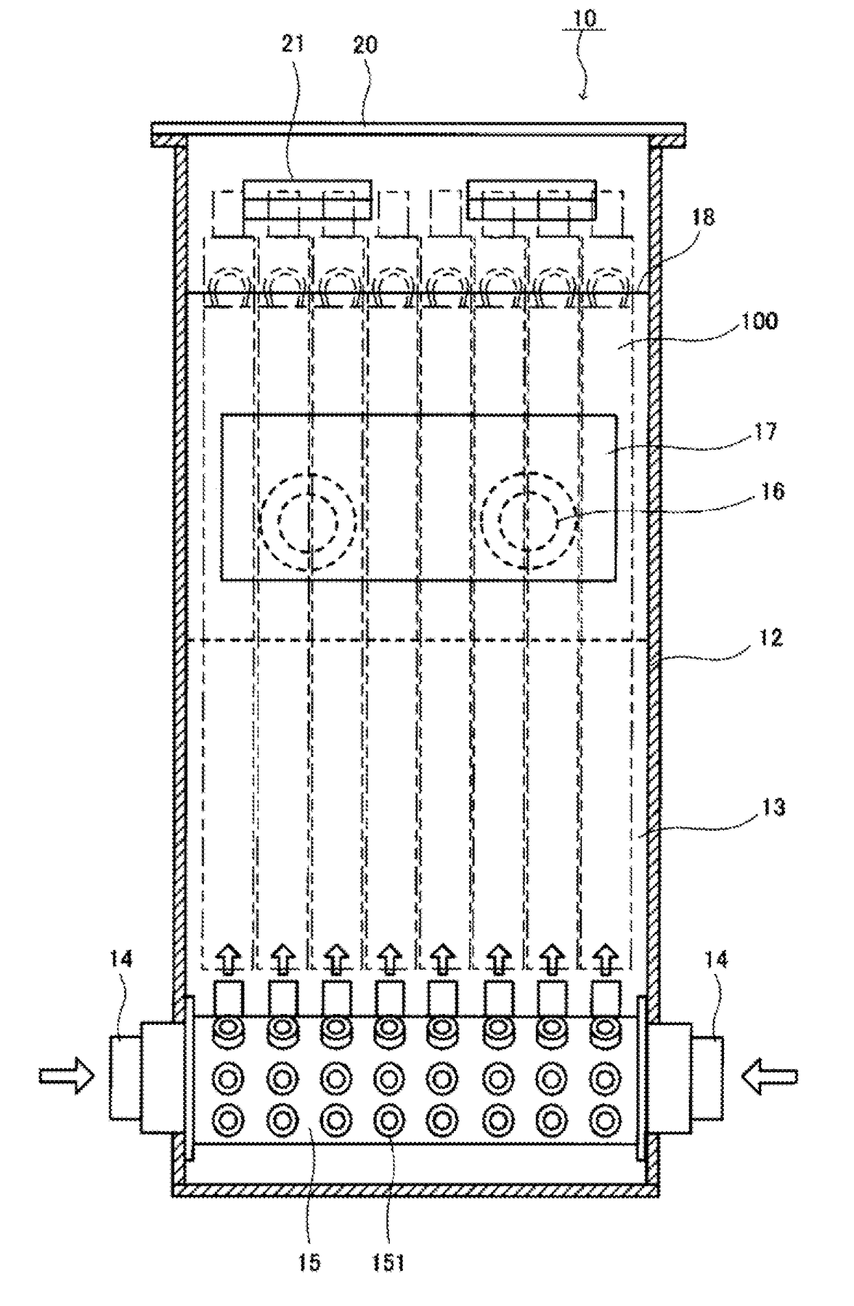
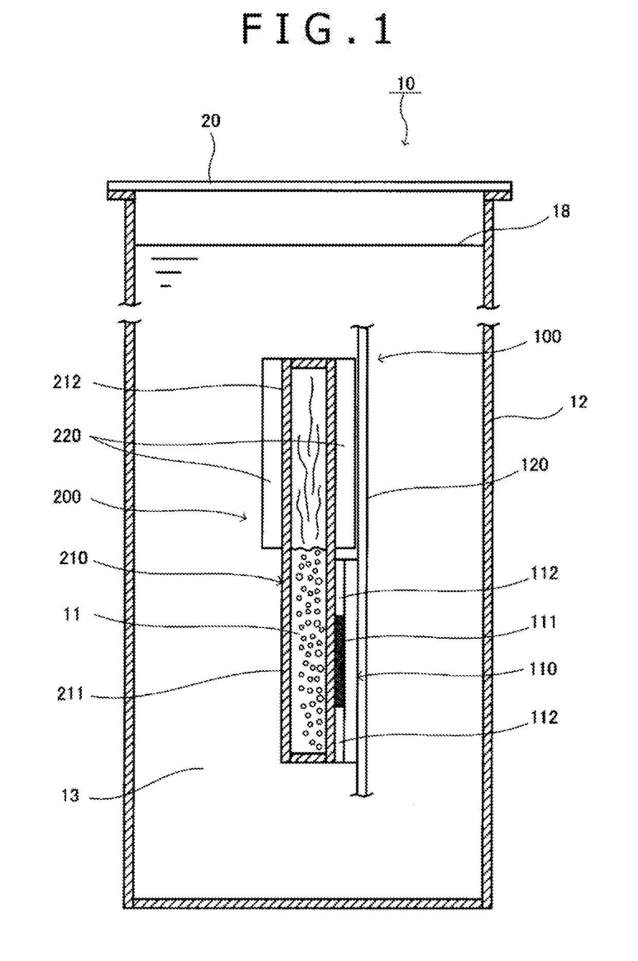
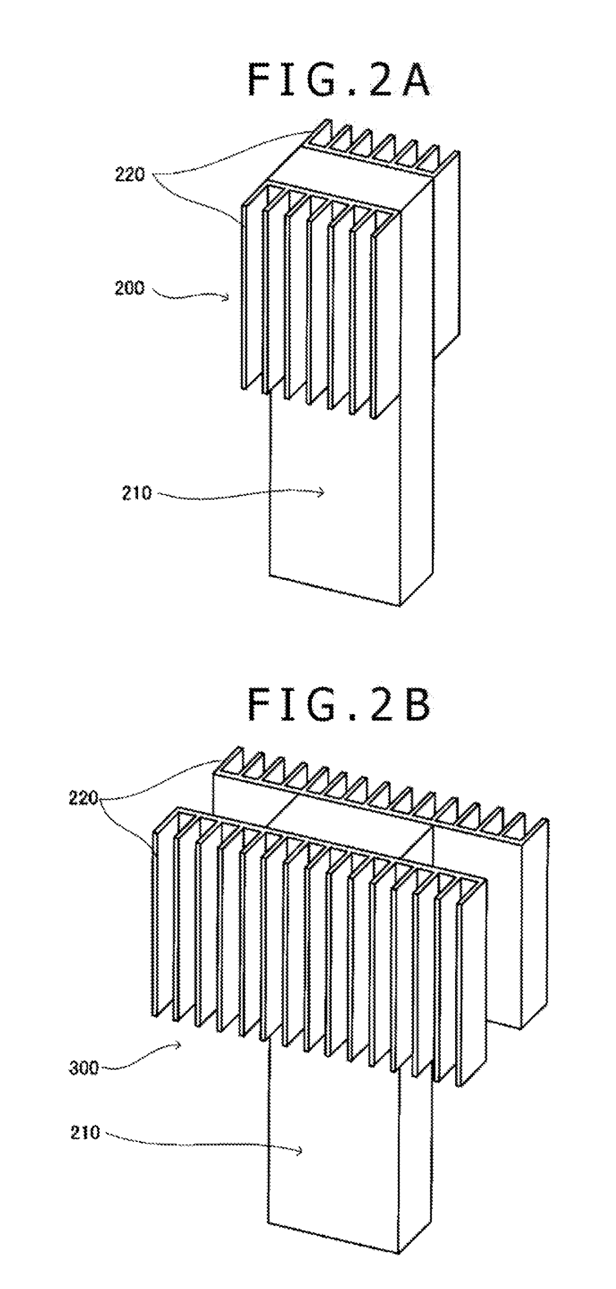
[0035]In the following, a preferred embodiment of a cooling system according to the present invention will be described in detail with reference to the drawings. In the description of the embodiment, first, the configuration of the main components of a cooling system will be described with reference to FIGS. 1, 2A, 2B, and 2C. In the system, an electronic device having a processor, which is a heat generating component, mounted on a board is housed in a cooling bath for cooling. The processor includes a die (a semiconductor chip) and a heat spreader surrounding the die. Subsequently, referring to FIGS. 3 and 4, the configuration of a high-density cooling system will be described. As the electronic device, an electronic device in a structure below is provided. Four processor boards each mounted with a plurality of processors are provided. These processor boards are disposed on one face of the electronic device. This makes one unit. Eight units of the electronic devices in total are hi...


PUM


Abstract

There are provided a cooling system and a cooling method that are simple and efficient and improve cooling performances for an electronic device. A cooling system (10) includes a cooling bath (12). In the open space of the cooling bath (12), a second coolant (13) with a boiling point (T2) is contained. In the open space of the cooling bath (12), an electronic device (100) is housed. The electronic device (100) is mounted with a processor (110) as a heat generating component on a board (120). The electronic device (100) is immersed in the second coolant 13. A boiling cooling device (200) is a cooling device thermally connected to the processor (110), and encloses a first coolant 11 with a boiling point (T1) (where T2>T1).

Description

TECHNICAL FIELD[0001]The present invention relates to a cooling system for an electronic device, and more specifically to a cooling system and a cooling method for an electronic device, which efficiently cool an electronic device that is requested to operate in ultra-high performance mode or to operate stably on supercomputers, at data centers, or the like, and generates a large quantity of heat.BACKGROUND ART[0002]One of the biggest problems to determine the limits of performances of today's supercomputers is power consumption. The importance of studies on the energy efficiency of supercomputers is already widely recognized. In other words, floating point operations per second per watt (FLOPS / Watt) is one indicator to evaluate supercomputers. In data centers, it is estimated that electric power is used for cooling by about 45% of the power consumption in the entire data centers. There is an increasing demand to decrease power consumption by improving cooling efficiency.[0003]Conven...

Claims


Application Information

Patent Timeline
IPC IPC(8): H05K7/20F28D15/02H01L23/427G06F1/20F25D9/00
CPCH05K7/20236H01L23/427F28D15/02G06F1/20H01L2924/0002F25D9/00H05K7/20254H05K7/20281F28D1/0213F28D15/0275F28D21/0017G06F2200/201H01L23/44H05K7/20772H01L2924/00
Inventor SAITO, MOTOAKI
Owner EXASCALER
Why Eureka
Try Eureka