
Artificial ground freezing method and artificial ground freezing system

a technology of artificial ground and freezing method, which is applied in the direction of shaft sinking, shaft equipment, mining structures, etc., can solve the problems of large amount of energy, high rental cost increased operating costs of brine circulation pumps, so as to reduce the cross-section area of circulation pipes, reduce the cost of cooling and condensing coolant gas, and improve thermal efficiency

Active Publication Date: 2017-12-07
CHEM GROUTING
View PDF0 Cites 8 Cited by
  • Summary
  • Abstract
  • Description
  • Claims
  • Application Information

AI Technical Summary

Benefits of technology

The present invention is an improved system for freezing underground materials using liquid-phase carbon dioxide as a coolant. This system has several technical effects. Firstly, liquid-phase carbon dioxide has better thermal efficiency than brine coolant, meaning it can absorb more heat and freeze the ground more effectively. Secondly, with the coolant circulating in a closed system, carbon dioxide gas is not released into the atmosphere, reducing costs and keeping the construction site safe. Lastly, liquid-phase carbon dioxide has a small coefficient of viscosity, which allows for faster circulation and reduces the size of the coolant circulation pipes. This results in a smaller diameter of the freeze pipe, a longer length of the coolant circulation pipe, and a reduction in the coolant circulation pump energy needs. The coolant circulation pipes can be manufactured in a plant and transported to the construction site, reducing construction costs and preventing leakage. Overall, this invention offers a more efficient, cost-effective, and safety-oriented solution for freezing underground materials.

Problems solved by technology

For artificial ground freezing methods applying to such objects, since larger and deeper underground structures are required and therefore extremely large scale of freezing is required, it is necessary to maintain ground freezing work in several months or even several years.
In a case that artificial ground freezing method is applied for ground improvement work using tunnel boring machines in the launch areas and the arrival areas of TBM shaft, connecting passage between underground tunnels or underground tunnel connecting areas, there is a problem that large quantity of energy is necessary in order to cool a large amount of brine in low temperature, if a scale of ground size to be frozen is extremely large.
For these requirements, freeze pipes with a large diameter are necessary, and therefore, higher expenses for boring and pipe materials are required.
Furthermore, higher capacity in brine circulation pump being required leading to higher rental cost of brine circulation pump and larger pump driving energy, and therefore, economically disadvantage generates.
In a case that a diameter of freeze pipe is large, there is a problem that truck transportation cost and rental cost of a crane for pipe lifting are expensive, large effort for welding is required, and therefore, economically disadvantage is generated.
Also, there are other economic problems that a time periods of steps for boring and for placing freeze pipes of underground construction become longer respectively and the entire construction costs are extremely expensive.
Also, if underground brine leakage from defective welded freeze pipes generates, the ground around the leakage position fails to sufficiently freeze, water leakage is generated and insufficient ground strength will not be accomplished, and therefore, it is difficult to carry out subsequent construction work.
Here, when the neighboring ground to the injection point of liquefied carbon dioxide starts to be frozen, since it is difficult to deliver liquefied carbon dioxide behind the frozen ground, there is a problem that it is impossible to form frozen soil with a temperature being equal to or less than −10° C.
In a prior art method in which a double-pipe structure is used and ground is frozen by utilizing liquid-phase nitrogen with an extremely low boiling point (Patent Document 2), since nitrogen gas is eventually released as “waste” into the atmosphere, there is an economically disadvantage in a case that a scale of the method being carried out is large and consumption quantity of nitrogen gas is large.

Method used


Image

  • Artificial ground freezing method and artificial ground freezing system
  • Artificial ground freezing method and artificial ground freezing system
  • Artificial ground freezing method and artificial ground freezing system

Examples


first embodiment

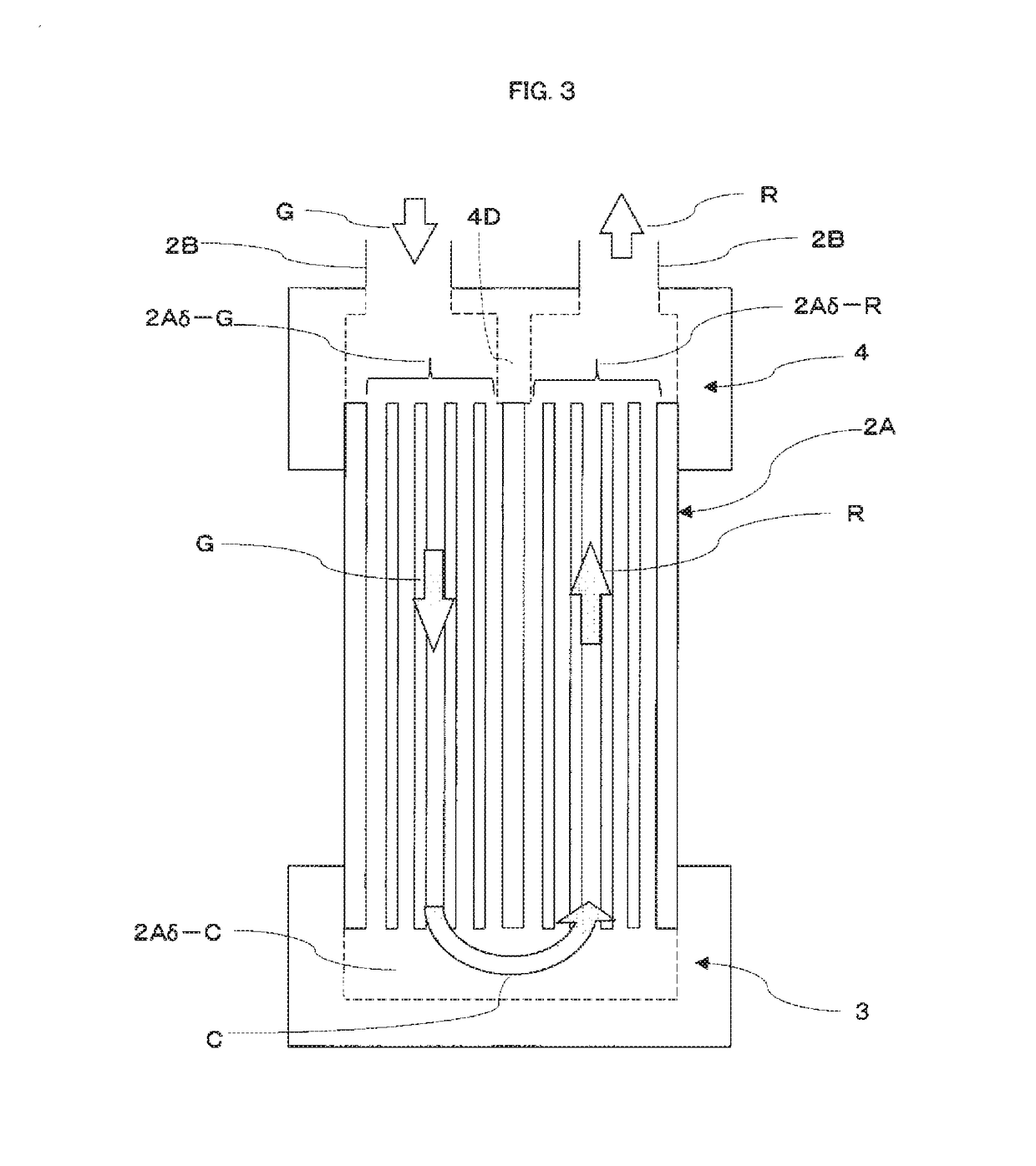
[0101]According to the present invention, when a first coolant circulation pipe 2A is provided in a freeze pipe 1 (casing), as shown in FIG. 3, a bottom socket 3 (plugging member) is brazed on the bottom (underground end) of the first coolant circulation pipe 2A (micro channel). The connection between the first coolant circulation pipe 2A and the bottom socket 3, however, may be carried out by means of a non-brazing method.

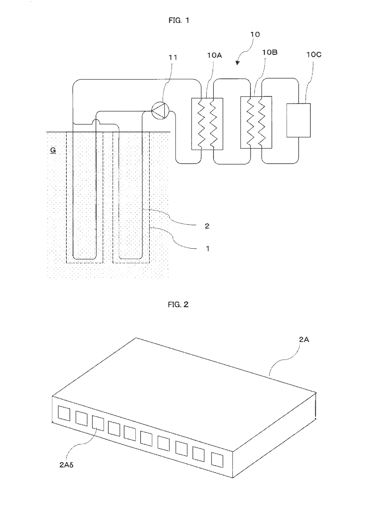
[0102]In FIG. 3, micro-coolant passages 2Aδ-G provided on the left side in the first coolant circulation pipe 2A (5 micro-coolant passages provided on the left side out of 10 micro-coolant passages 2Aδ in FIG. 3) correspond to a coolant supply side, and micro-coolant passages 2Aδ-R provided on the right side (5 micro-coolant passages provided on the right side out of 10 micro-coolant passages 2Aδ) correspond to a coolant return side that returns to a coolant apparatus 10 (FIG. 1).

[0103]In FIG. 3, the micro-coolant passages 2Aδ-G provided on the left side and the m...

second embodiment

[0141]the present invention will be described with reference to FIGS. 6 to 9.

[0142]In the first embodiment shown in FIGS. 3 to 5, a first coolant circulation pipe 2A, composed of micro-coolant passages, is provided only near the bottom in a freeze pipe 1 (casing), and second coolant circulation pipes 2B (pipes with a circular cross-section) connected with the first coolant circulation pipe 2A through a top socket 4 (connecting member) are also inserted into the freeze pipe 1 (casing).

[0143]On the other hand, in the second embodiment, the first coolant circulation pipe 2A (micro channel) is inserted into a freeze pipe 1 (casing) throughout a vertical direction area (in vertical direction in FIG. 6) corresponding to the freeze pipe 1, while second coolant circulation pipes 2B with a circular cross-section are not inserted into the freeze pipe 1 (casing).

[0144]In FIG. 6, the first coolant circulation pipe 2A (micro channel) is provided along the freeze pipe 1 (casing) vertically.

[0145]...

third embodiment

[0172]the present invention will be described with reference to FIGS. 11 to 14.

[0173]In FIG. 11, a coolant circulation pipe (micro channel) used in the third embodiment is denoted as numeral “3C.” The coolant circulation pipe 3C is entirely formed of a hollow cylinder (pipe), and a plurality of micro-coolant passages 3Cδ-G (8 micro-coolant passages in FIG. 11) are formed in a radially outwardly located region. A radially inwardly located hollow portion 3Cδ-R constructs a coolant return path for returning a coolant to a coolant apparatus 10 (shown in FIG. 1), and also, an internal diameter of the radially inwardly located hollow portion 3Cδ-R is set so as to be larger than an internal diameter of a micro-coolant passages 3C δ-G.

[0174]The hollow portion of the coolant circulation pipe 3C may be written by phrases “a coolant return path 3Cδ-R” or “a coolant path 3C—5-R”. As mentioned above, a coolant circulation pipe 3C, in the form of hollow cylinder (pipe), may herein be denoted as “...


PUM


Abstract

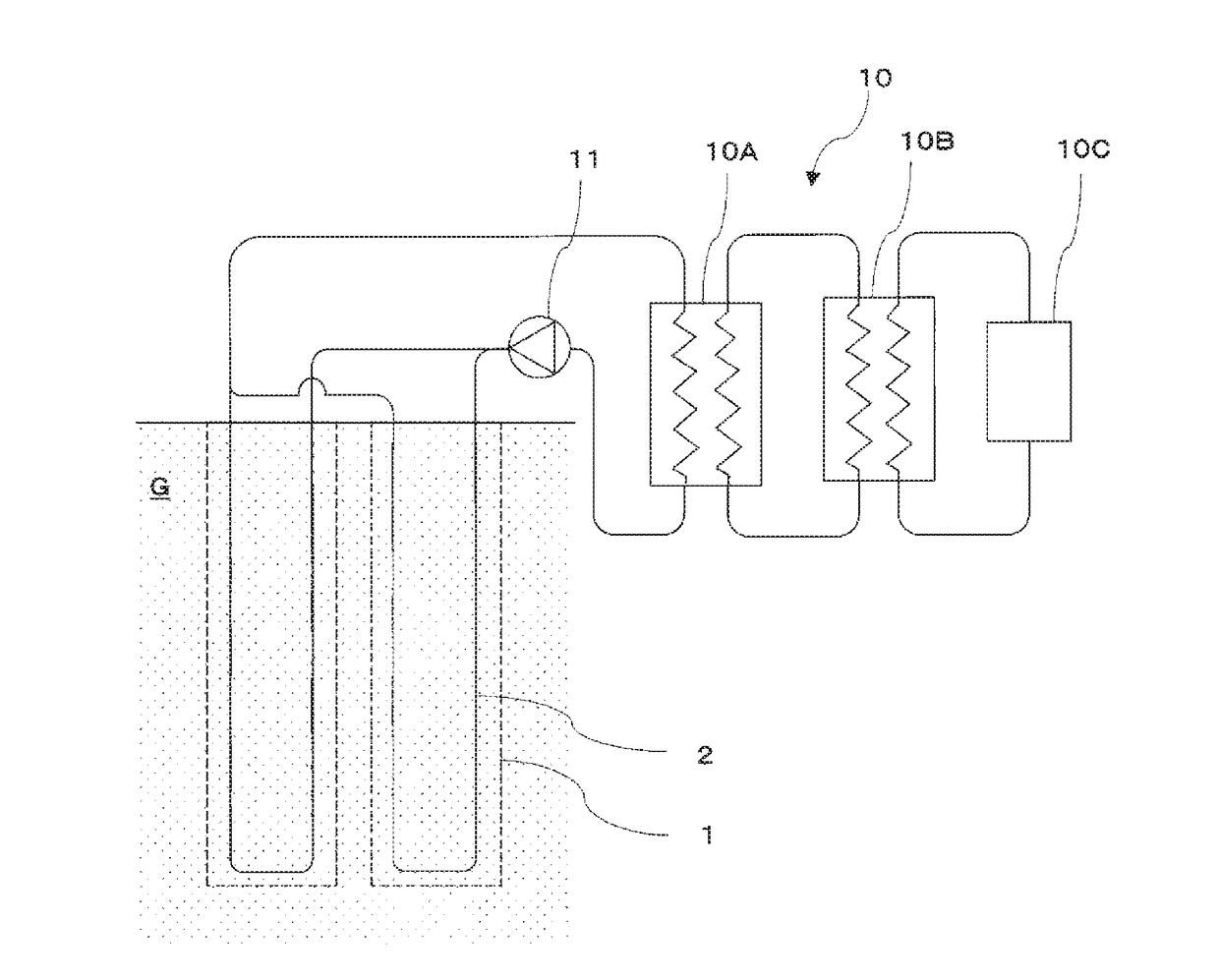
The purpose of the present invention is to provide an artificial ground freezing method having good coolant thermal efficiency without a gas-phase coolant being released into the ground or into the air. For that purpose, the present invention has: a freeze pipe (1: casing) for freezing the ground buried in the ground and a coolant circulation pipe (2) provided on the inside of the freeze pipe (1), wherein the coolant flowing inside the coolant circulation pipe (2) is carbon dioxide; and a coolant apparatus (10) that cools and supplies the carbon dioxide to the coolant circulation pipe (2), the coolant circulation pipe (2) comprising a first coolant circulation pipe (2A) on which a plurality of micro-coolant passages (2A delta) is formed, wherein the tip portion (tip portion in the ground) of the first coolant circulation pipe (2A) is connected to a plugging member (3: bottom socket) that connects the plurality of micro-coolant passages (2A delta) of the first coolant circulation pipe (2A) to a coolant supply side and coolant return side.

Description

TECHNICAL FIELD[0001]The present invention relates to an artificial ground freezing technology.BACKGROUND ART[0002]Artificial ground freezing methods have been used for ground improvement work using tunnel boring machine (TBM) for the launch area and the arrival are of TBM shafts, cross passage between tunnels, connection in underground tunnels, and enlargement of TBM tunnel (space). For artificial ground freezing methods applying to such objects, since larger and deeper underground structures are required and therefore extremely large scale of freezing is required, it is necessary to maintain ground freezing work in several months or even several years.[0003]As conventionally known, strength of frozen ground depends on the freezing temperature with negative correlation, that is, the strength increases as the temperature descends. Since water cutoff and pressure-proof properties are desired in said frozen ground, it is necessary to maintain a freezing temperature equal to or less th...

Claims


Application Information

Patent Timeline
Patent Type & Authority Applications(United States)
IPC IPC(8): E02D3/115E02D19/14E21D1/12E21D9/04
CPCE02D3/115E21D9/04E21D1/12E02D19/14
Inventor TACHIWADA, YUICHITSUCHIYA, TSUTOMUARIIZUMI, TAKERUSOMA, HIROSHI
Owner CHEM GROUTING
Learn More