
Industrial fabric, method for producing a nonwoven, and use of an industrial fabric

a technology of industrial fabric and nonwoven, which is applied in the field of industrial fabric, can solve the problems of inadequate wetting of the polymer dispersion having the bonding properties, the inability to heat the fibers forming the nonwoven web, and the inability to meet the needs of woven fabrics, etc., and achieves the effects of low tendency to adhere, long service life and small fabric thickness

Inactive Publication Date: 2017-12-14
ASTENJOHNSON PGMBH
View PDF2 Cites 0 Cited by
  • Summary
  • Abstract
  • Description
  • Claims
  • Application Information

AI Technical Summary

Benefits of technology

The invention is about an improved industrial fabric for use as a conveyor belt in nonwoven production. The fabric is designed to have low tendency to adhere to fibers, leading to longer service life. It also has a small fabric thickness, smooth surface, and reduced production costs. The fabric has a unique design with only a single CMD layer, resulting in increased flexibility and the ability to realize smaller radii on deflection rollers. The fabric is produced economically because there are not multiple layers of CMD threads. The use of a special "anti-stick material" can be limited to the amount necessary to achieve the desired effect, and a base material with good mechanical properties and low price can be used to form a coating on the outer layer of the fabric. The anti-stick properties are also important in the area of the spiral seam.

Problems solved by technology

However, despite the previously mentioned microstructuring of the thread surfaces, previously known conveyor belts still have too great a tendency toward adhesion and soiling.
This leads, in turn, to inadequate heating of the fibers forming the nonwoven web, so that the melting of the bicomponent fibers and / or the wetting of the polymer dispersion having the bonding properties is inadequate.
This results in insufficient bonding of the fibers of the nonwoven, so that the strength of the end product is not satisfactory.
Replacing the conveyor belt causes not only costs due to the necessary purchase of a new conveyor belt, but also due to the stoppage of the production system during the belt replacement.
One disadvantage of the two-layer fabric known from US 2014 / 0127959 A1, however, is the high costs of its production and the large fabric thickness.
Because there are only a limited number of materials with a high surface energy, as is required in the present case, and the relevant materials are often relatively expensive, the use of this special “anti-stick material” should be limited to the amount necessary for achieving the desired effect.

Method used


Image

  • Industrial fabric, method for producing a nonwoven, and use of an industrial fabric
  • Industrial fabric, method for producing a nonwoven, and use of an industrial fabric
  • Industrial fabric, method for producing a nonwoven, and use of an industrial fabric

Examples


Embodiment Construction

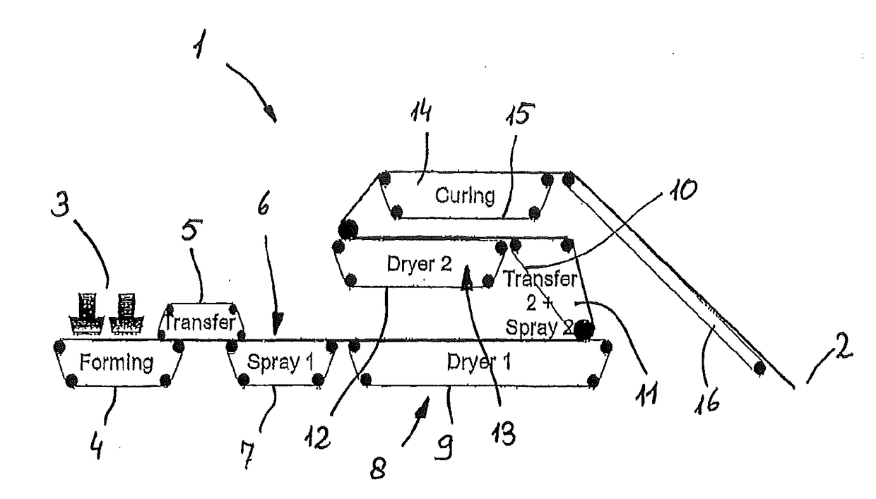
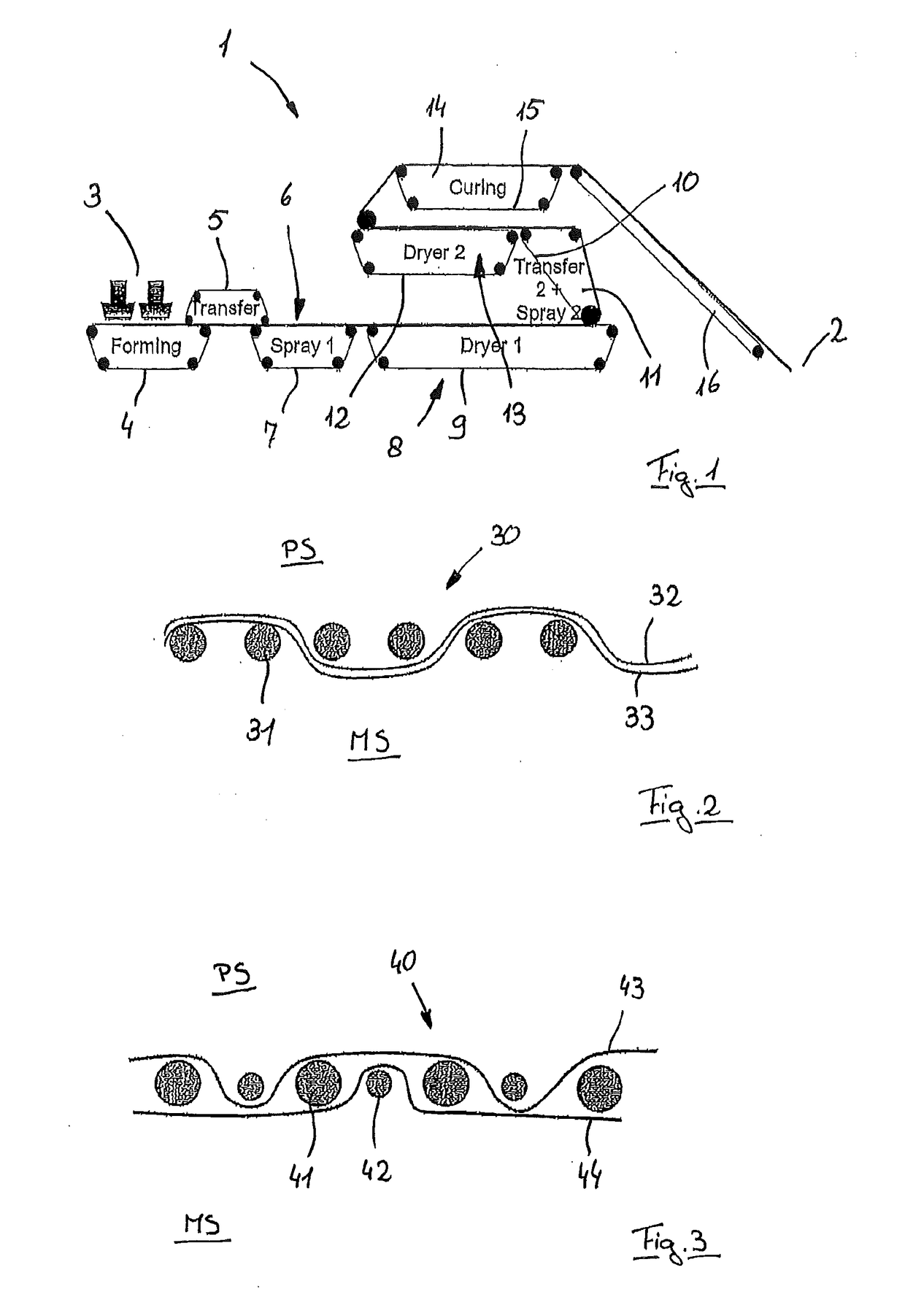
[0043]A system 1 shown in FIG. 1 is used for producing an aerodynamically formed and both thermally and also chemically cured nonwoven that leaves the system 1 at the position 2 as an endless web. The nonwoven is formed from a fiber pulp, mixed with two-component fibers and a very water-absorbent plastic granulate. The two-component fibers have a core made from polypropylene with a higher melting point and a casing made from polyethylene surrounding the core with a lower melting point. The starting materials are fed by means of a feeder 3 to a forming belt 4 where a material layer is formed. With the help of a transfer belt 5, the nonwoven web is transferred to a spraying device 6 where a coating of a polymer dispersion with bonding properties is applied. For passing through the spraying device 6, the nonwoven web is transported by a belt 7.

[0044]Downstream of the spraying device 6, the nonwoven web is fed into a first drying device 8 (furnace) where the web is transported by a conv...


PUM

PropertyMeasurementUnit
Fractionaaaaaaaaaa
Angleaaaaaaaaaa
Areaaaaaaaaaaa

Abstract

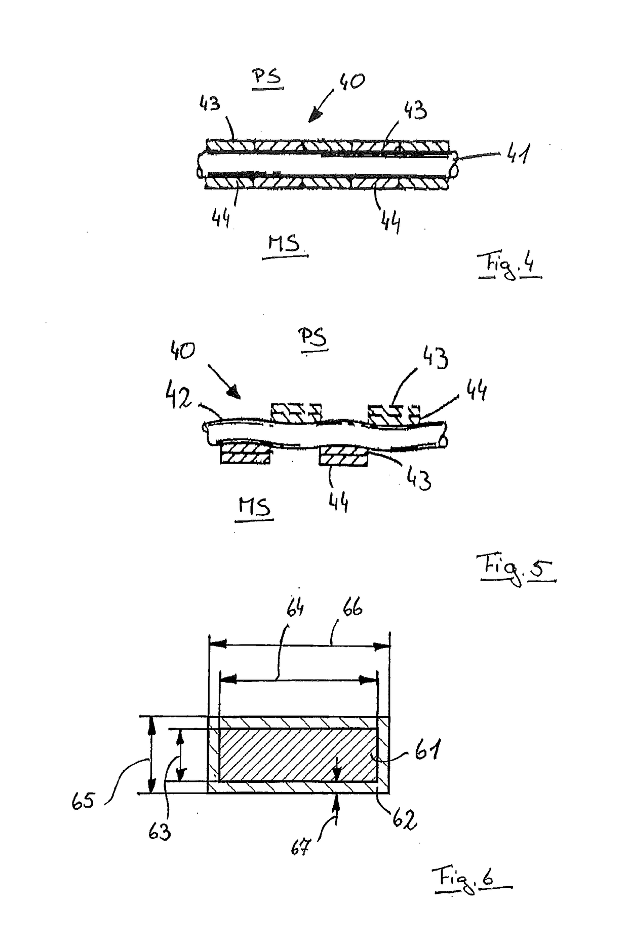
An industrial fabric (30, 40, 45) is provided, in particular for transporting a nonwoven web while producing same, having a product side (PS), which is in contact with the nonwoven, and a machine side (MS), which is in contact with transport devices of a system (1) for producing the nonwoven. The fabric (30, 40, 45) has MD threads (32, 33, 43, 44, 48, 50), which run in the running direction of the nonwoven web, and CMD threads (31, 41, 42, 52), which run perpendicularly to the MD threads, said threads being woven together. At least two layers of MD threads (32, 33, 43, 44, 48, 50) are provided which are stacked one over the other in pairs and form product contact MD threads (32, 43, 50) and non-product contact MD threads (33, 44, 48). At least the material of each product contact MD thread (32, 43, 50) facing the product side (PS) forms a contact angle, measured according to the Wilhelmy plate method, of at least 80°, preferably at least 90°, more preferably at least 100°. In order to prevent the adhesion of threads to the fabric (30, 40, 45) and in order to reduce the air permeability, the fabric has a single layer of CMD threads (31, 41, 42, 52), and the cross-section of each product contact MD thread (32, 43, 50) has at least two regions, a first region of which is formed of the first material and a second region of which is formed of the second material. A substantial proportion, preferably a predominant proportion, of a tensile force acting on each product contact MD thread (32, 43, 50) can be transmitted from the second region, and the cross-section of the product contact MD threads (32, 43, 50) have a second region in the form of a core (61) and a first region in the form of a casing (62) which surrounds the core (61). The product MD threads (32, 43, 50) are preferably coextruded or are extruded in two successive steps. The MD threads (32, 33, 43, 44, 48, 50) have a flattened cross-section, preferably a rectangular cross-section, wherein a ratio of a height of the cross-section to a width of the cross-section preferably ranges from 1:1.2 to 1:10, preferably from 1:1.5 to 1:4. The invention further relates to a method for producing a nonwoven and to the use of an industrial fabric (30, 40, 45).

Description

FIELD OF THE INVENTION[0001]The invention relates to an industrial fabric, especially for transporting a web of a nonwoven during its production, with a product side that is in contact with the nonwoven and a machine side that is in contact with conveying devices of a machine for producing the nonwoven, wherein the fabric has MD threads oriented in the running direction of the web of the nonwoven and CMD threads that are oriented perpendicular to the MD threads and are interwoven with each other and there are at least two layers of MD threads that are arranged stacked in pairs one above and below each other, and form product contact MD threads and non-product contact MD threads, wherein at least the surface of the respective product contact MD threads facing the product side has a first material that has a contact angle, measured according to the Wilhelmy plate method, of at least 80°, preferably at least 90°.[0002]In addition, the invention relates to a method for producing a nonwo...

Claims


Application Information

Patent Timeline
IPC IPC(8): D03D1/00D04H13/00D03D15/00
CPCD03D1/0094D03D15/0088D04H13/00D03D15/0027D03D15/0094D03D13/008D04H1/70D04H3/02D03D15/43D03D15/46D03D15/292
Inventor KUCKART, DIETERDEBYSER, PASCALMONNERIE, JEAN-LOUIS
Owner ASTENJOHNSON PGMBH
Learn More