
Methods for the vapor phase deposition of polymer thin films

a technology of vapor phase and polymer, which is applied in the direction of liquid surface applicators, coatings, special surfaces, etc., can solve the problems of destroying the functionality imparted by roughness, limiting heat transfer, and needing to provide a heated filament adjacent to the substra

Inactive Publication Date: 2018-01-11
MASSACHUSETTS INST OF TECH
View PDF4 Cites 4 Cited by
  • Summary
  • Abstract
  • Description
  • Claims
  • Application Information

AI Technical Summary

Benefits of technology

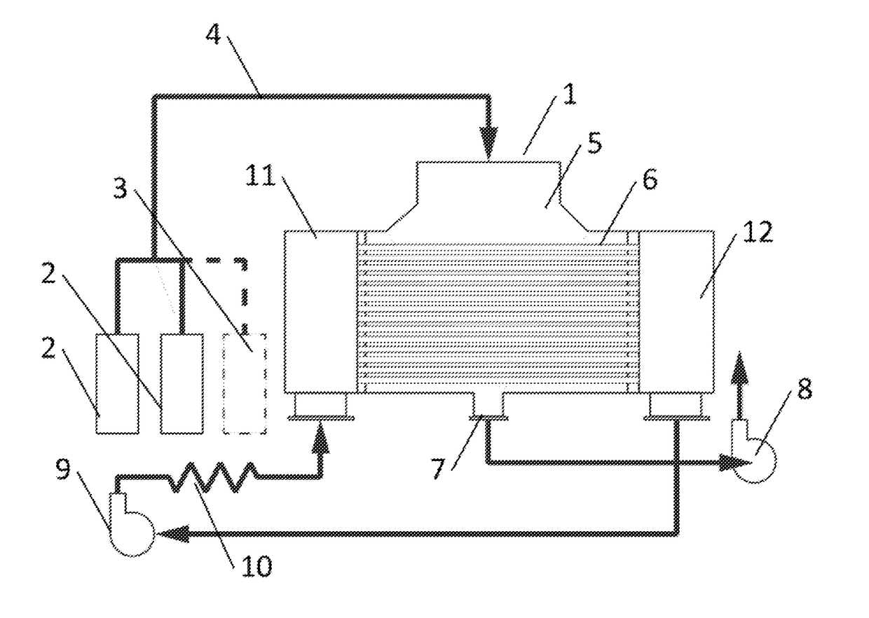
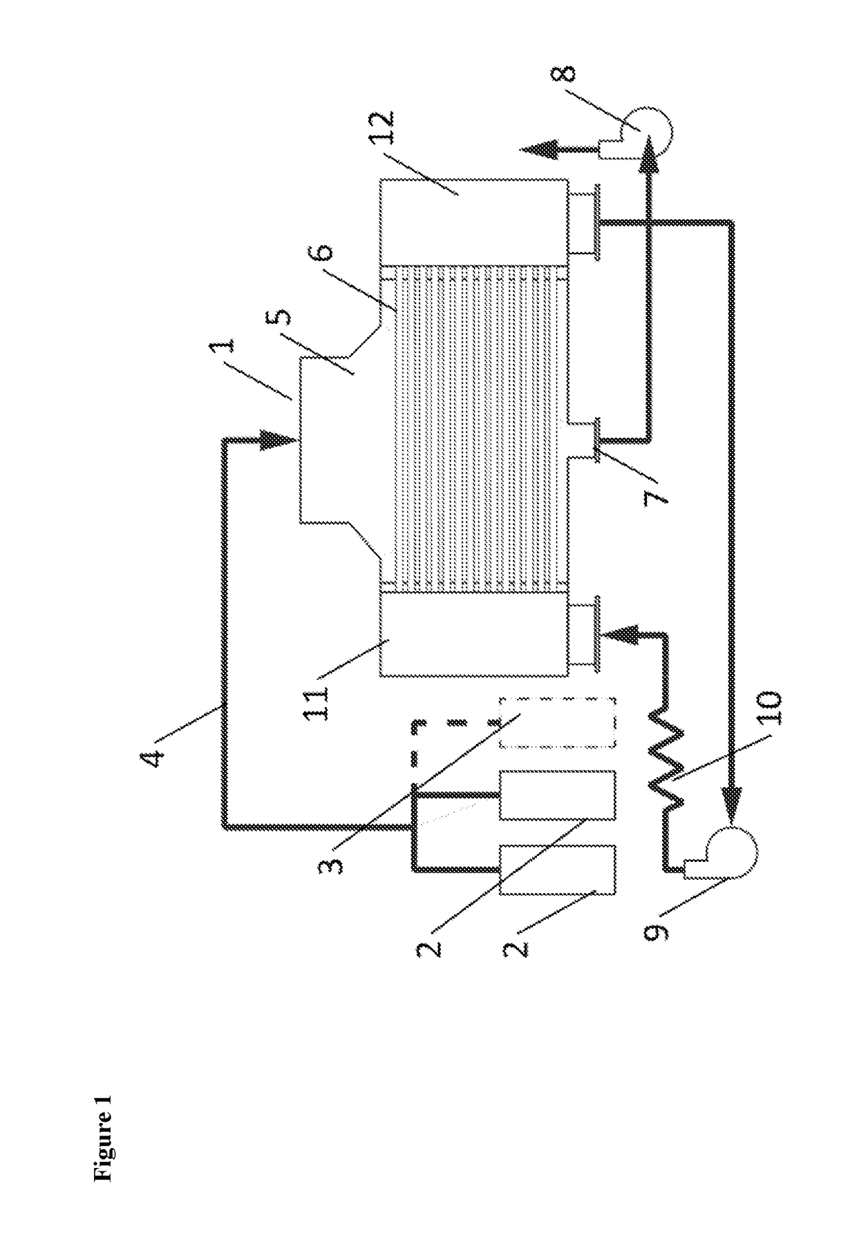
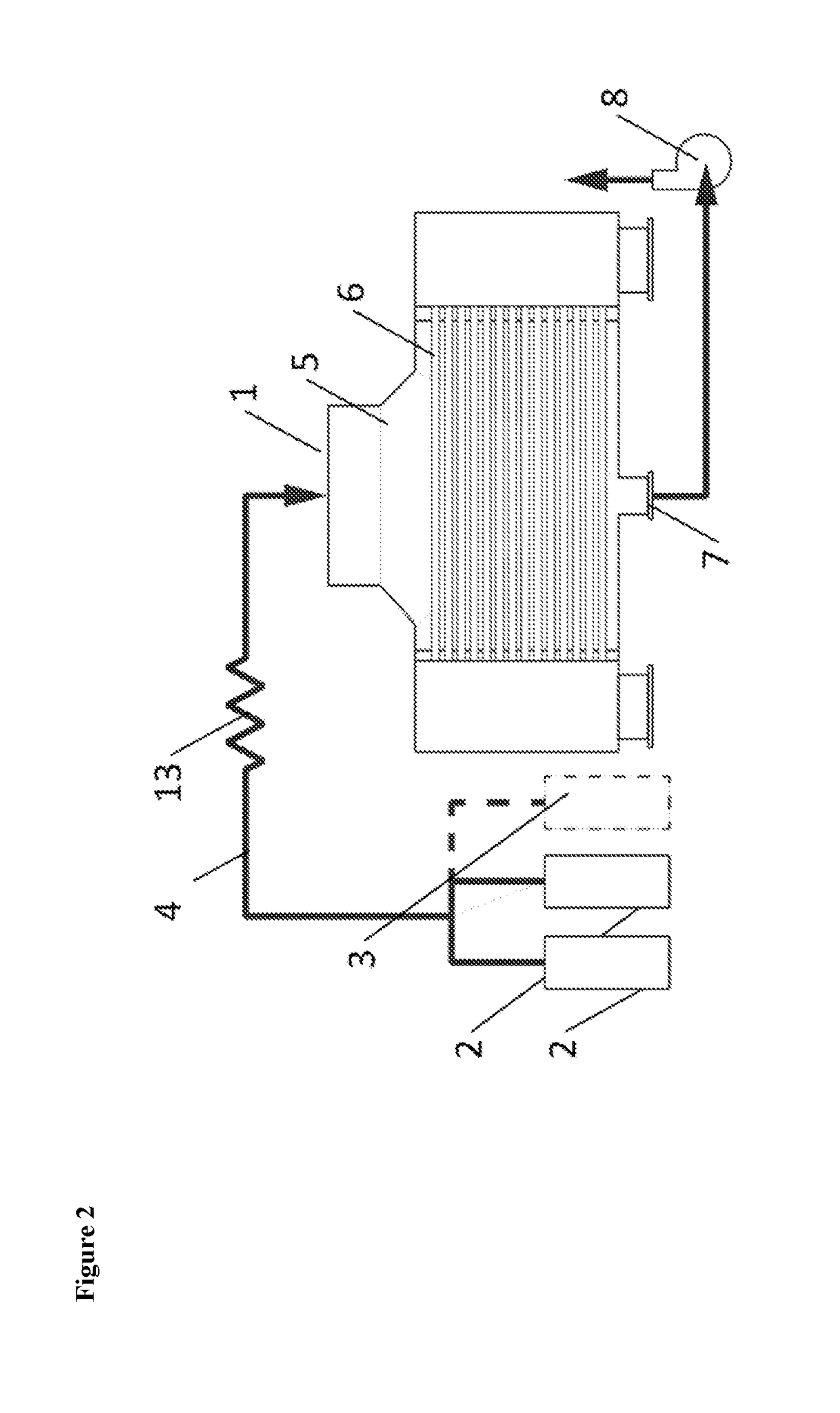
The present invention provides a method of depositing a coating on an article by introducing a gaseous mixture of reagents into the interior volume of the article and heating the gaseous mixture. The gaseous mixture can be heated to a temperature from about 50°C to about 150°C while being confined in the interior volume of the article. The heated gaseous mixture can be introduced at a pressure that is temporarily less than one atmosphere. The invention also provides a method of introducing a heated gaseous mixture into the interior volume of an article and heating the interior surface of the article prior to introducing the gaseous mixture. The invention can be used to deposit various coatings on the interior and exterior surfaces of articles.

Problems solved by technology

However, these methods result in relatively thick films, typically greater than 1 μm in thickness, and sometimes as thick as 1000 μm, which presents a significant barrier to heat transfer because of the thermal resistance of the coating.
Coatings deposited via e.g. spray-coating or dip-coating will lead to thick surfaces that completely cover the roughness features, thereby destroying the functionality imparted by the roughness.
One drawback of conventional iCVD approaches is the need to provide a heated filament adjacent to the substrate.
Since heat exchangers are commonly configured as enclosed bodies with complicated internal geometries, it is difficult to place filaments such that a uniform coating is applied to the desired surfaces.
However, such a technique would require extensive modification of existing heat exchangers to provide the necessary electrical isolation between the tube sheets and the other components of the heat exchanger.
However, these coatings rely on chromium adhesion layers to survive under a steam environment.
It would, therefore, be difficult to coat complex geometries, such as a heat exchanger bundle, without providing extensive flow manifolds or the like.

Method used


Image

  • Methods for the vapor phase deposition of polymer thin films
  • Methods for the vapor phase deposition of polymer thin films
  • Methods for the vapor phase deposition of polymer thin films

Examples


example 1

Deposition Activated by a Heated Reactor Body

[0099]A polymeric coating was deposited onto a piece of silicon without the use of filaments. The deposition was carried out in a vacuum chamber in which the surface temperatures were controlled. The chamber was evacuated down to a base pressure of less than 0.05 Torr. All reactor chamber walls and surfaces were heated to around 150° C. The substrate surface was held at a temperature of about 35° C. Divinylbenzene (DVB) was used as the monomer, and preheated in a glass jar outside the reactor to 80° C. An inhibitor, 4-hydroxy TEMPO, was used to minimize self-polymerization of the DVB in the glass jar. A free radical initiator, di-tert-butylperoxide (TBPO), was also used. DVB and TBPO were flowed into the chamber through heated lines at 0.6 and 3.8 sccm, respectively. The throttle valve, which exhausts to the pump, was used to maintain the chamber pressure at 1.75 Torr. The reaction was allowed to proceed for 105 minutes. After this time, ...

example 2

Deposition Activated by Heated Substrate (Prophetic)

[0100]This example outlines an experiment to deposit a polymer coating without the use of filaments. The deposition is carried out in a vacuum chamber in which surface temperatures are controlled. The chamber is evacuated down to a base pressure of less than 0.05 Torr. The target surface within the chamber is heated to a temperature of 120° C. All other chamber walls and surfaces are heated to around 70° C. Divinylbenzene (DVB) is used as the monomer and heated in a glass jar outside the reactor to 80° C. An inhibitor is used to minimize the self-polymerization of the DVB in the glass jar. DVB is flowed into the vacuum chamber through heated lines. The throttle valve, which exhausts to the pump, is closed, and the chamber pressure increases due to DVB flow into the chamber. Once the pressure reaches 3 Torr, the DVB flow is stopped. A low-temperature free radical initiator, such as tert-butylperoxybenzoate (TBPOB), is then be delive...

example 3

Deposition Activated by Heated Lines

[0101]This example outlines an experiment to deposit a polymer coating without the use of filaments. In this Example, polymerizations were conducted in a cylindrical vacuum chamber (described in Im, S.; Gleason. K.; Macromolecules, 2007, 40, 6552-6556). Heat tape (Omega Engineering) was used to heat the desired surfaces on the air side. The reactor body was maintained at 70° C., which was well below the activation temperature of the materials used. The target surface within the chamber was a Si wafer held to an inverted stage that was back-cooled at a temperature of ˜25° C. using a recirculating chiller (VWR). Reactor pressure was maintained at 2 Torr using a throttle valve (MKS Instruments). Di-tert-butylperoxide (TBPO) was used as the radical initiator and divinylbenzene (DVB) was used as the monomer. The TBPO was held in an unheated glass jar outside the reactor, and delivered to the chamber through lines heated at 180° C. and at a flowrate of ...


PUM

PropertyMeasurementUnit
Temperatureaaaaaaaaaa

Abstract

Disclosed are methods for forming thin polymeric films on a surface of an article by deposition from the vapor phase. In certain embodiments, the method comprises depositing the polymeric film in situ inside a space or enclosure contained within the article. In other embodiments, the method comprises depositing a film from vapor phase by thermal degradation of an initiator precursor without the need for an external filament.

Description

RELATED APPLICATION[0001]This application claims the benefit of priority to U.S. Provisional Patent Application Ser. No. 62 / 109,866, filed Jan. 30, 2015; the contents of which are hereby incorporated by reference.BACKGROUND OF THE INVENTION[0002]In many applications, the performance or durability of a device may be significantly improved by applying a functional coating or film on the device. For example, heat exchanger coatings are currently employed to mitigate corrosion and formation of scale and fouling deposits. Additionally, liquid-repellent heat exchanger coatings may also be used to promote dropwise condensation. These coatings often must be applied to extremely large surface areas, such as tubing bundles in shell-and-tube heat exchangers, heat exchanger plates, and finned surfaces. Current commonly-used methods for depositing coatings across large areas include dip-coating and spraying. However, these methods result in relatively thick films, typically greater than 1 μm in ...

Claims


Application Information

Patent Timeline
IPC IPC(8): B05D1/00
CPCB05D1/60B05D2502/00B05D2506/10B05D5/083B05D7/22
Inventor PAXSON, ADAM T.BORRELLI, DAVID C.VARANASI, KRIPA K.GLEASON, KAREN K.
Owner MASSACHUSETTS INST OF TECH
Learn More