Novel syringe system for fluid separation

Active Publication Date: 2018-01-11
SOUTHERN ILLINOIS UNIVERSITY
View PDF7 Cites 4 Cited by
  • Summary
  • Abstract
  • Description
  • Claims
  • Application Information

AI Technical Summary

Benefits of technology

[0007]The abovementioned needs are solved by the present invention, which leverages a syringe system, preferably in combination with centrifugation, to enable fast liquid phase separation that allows the desired fat cells to be grafted into the body more quickly and with lower risk of contamination or fat cell damage. The present invention improves the separation and isolation of liquids with varying densities via a number of features. One such feature includes a means of separating liquids of different densities by allowing the less-dense liquids that form the top layer(s) of a separated solution to pass through a controllable opening in the device, effectively isolating the top layer(s) without having to use multiple syringe

Problems solved by technology

This can be a slow, time-consuming process, taking approximately twenty to thirty minutes to achieve appropriate separation.
This method is problematic because it is a complicated procedure, is time-consuming, and there is a greater risk of the fat cells becoming infected due to contact with the environment.
Methods of removing the oil layer from lipoaspirate solutions separated by gravity or centrifugation without the use of multiple containers and syringes remain inefficient and burdensome.
The oil is trapped above the fat layer and cannot be discharged from conventional syringes or containers without prolonged effor

Method used


Image

  • Novel syringe system for fluid separation
  • Novel syringe system for fluid separation
  • Novel syringe system for fluid separation

Examples


first embodiment

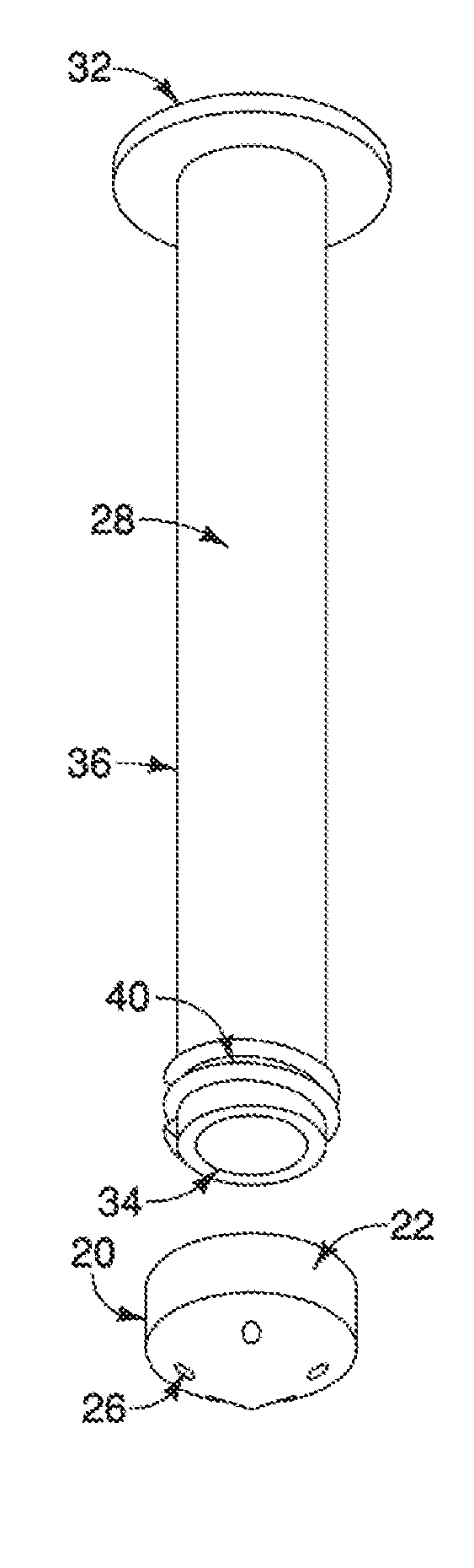
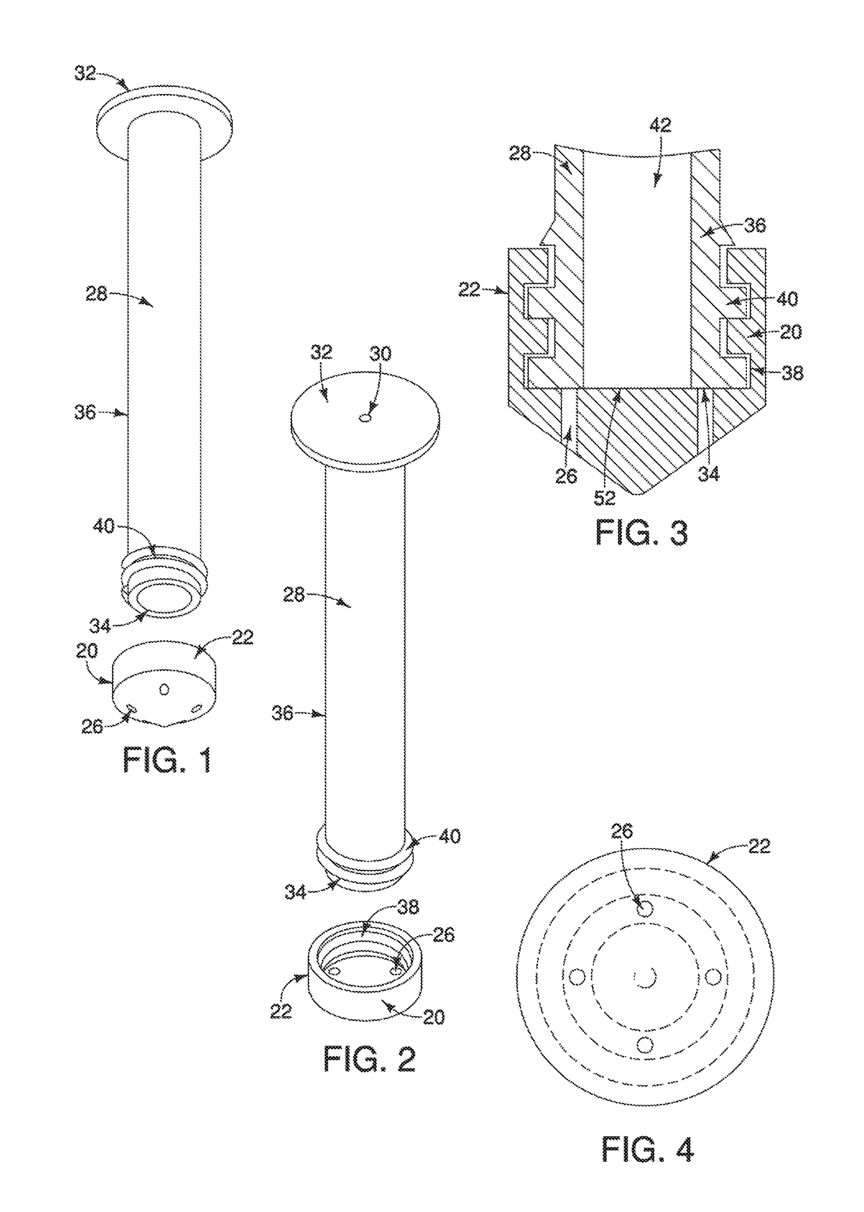
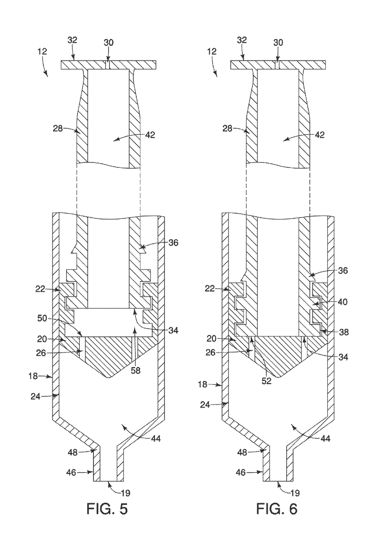
[0038]Now referring to FIGS. 1-6, a first embodiment is shown and is provided with the hollow syringe barrel 18 to contain the unseparated solution or separated layer(s), as applicable given the stage of processing and isolation of the material. The hollow syringe barrel 18 is preferably made of a hard durable material such as a rigid plastic, ceramic, or metal. Also provided is a perforated plunger seal 20 with an outer perimeter 22 that resides flush against an interior surface 24 of the hollow syringe barrel 18 and is provided with an at least one seal hole 26. The perforated plunger seal 20 is preferably made of a softer, more pliable material, such as a rubber or soft plastic, to create an effective seal against the interior surface 24 of the hollow syringe barrel 18. In a preferred embodiment, 2 to 4 seal holes are used, but 1 to more than 4 seal holes may be used.

[0039]A hollow plunging tube 28 is provided that is threadably coupled to the perforated plunger seal 20. The holl...

fourth embodiment

[0053]The removable stop cap 66 is insertable into the hollow plunging tube 28. The removable stop cap has a side relief hole ridge 76 that coincides with a hollow plunging tube notch 82 located in the hollow plunging tube 28. The side relief hole ridge 76 stabilizes the removable stop cap 66 when placed inside the hollow plunging tube 28. Then the removable stop cap rotates to a relief position wherein the at least one top portion relief hole 78 aligns with an at least one side relief hole 70 located on the hollow plunging tube 28, thereby creating a means to allow fluids to escape from within a hollow plunging tube cavity 42 of said hollow plunging tube 28. Conversely, the removable stop cap 66 is rotatable to a sealed position wherein the at least one top portion relief hole on the top portion misaligns with the at least one side relief hole located on the hollow plunging tube creating a seal within the hollow plunging tube cavity of the hollow plunging tube to prevent fluids fro...


PUM


Abstract

A syringe device for separating liquids of different densities is provided with a hollow syringe barrel, a perforated plunger seal with a seal hole, and a hollow plunging tube with a closed bottom with at least one tube hole. The perforated plunger seal has an outer perimeter that resides flush against an interior surface of the hollow syringe barrel. The tube hole is in operational relationship with the seal hole. Optionally, a relief hole is provided on a top portion of the hollow plunging tube to allow a user to create vacuum pressure as necessary.

Description

BACKGROUND OF THE INVENTION[0001]Autologous fat transfer, also known as fat grafting, has emerged as a widely used breast and facial reconstruction technique. Lipofilling, a form of fat grafting, has been used for several years, for example, to repair minor differences between a reconstructed breast and the non-reconstructed breast or to fill large dents in the body or face. Further uses include clinical applications to treat scleroderma, post-radiation skin damage, and skin rejuvenation. A surgeon performing a lipofilling procedure must go through several steps to obtain the fat cells necessary for grafting. After initial extraction by vacuum suction of raw lipoaspirate from the patient, the fat cells must be separated from the blood, debris, and oil in the lipoaspirate mixture.[0002]One way to accomplish separation of fat cells is to allow gravity to separate out the layers naturally. This can be a slow, time-consuming process, taking approximately twenty to thirty minutes to achi...

Claims


Application Information

Patent Timeline
IPC IPC(8): C12M1/00B01D17/02A61M5/315A61M5/34
CPCC12M47/04B01D17/0214A61M5/34A61M5/31566A61M5/31511B01D17/0217
Inventor GUPTA, ASHIMNEUMEISTER, MICHAEL W.CHO, SOHYUNG
Owner SOUTHERN ILLINOIS UNIVERSITY
Why Eureka
Try Eureka