Main spindle device for machine tool

a technology of machine tools and main spindles, which is applied in the direction of mechanical equipment, manufacturing tools, elastic bearings, etc., can solve the problems of inability to determine the appropriate rigidity and processing conditions, poor productivity, and various vibrations, so as to achieve the maximum vibration absorption efficiency of the vibration reducing members and reduce the effect of vibration during processing

Active Publication Date: 2018-01-25
OKUMA CORP
View PDF0 Cites 1 Cited by
  • Summary
  • Abstract
  • Description
  • Claims
  • Application Information

AI Technical Summary

Benefits of technology

[0008]The main spindle device for the machine tool according to the first aspect has a considerably low-price structure where the cushioning members are disposed between the main spindle and the main spindle built-in member, and the grooves for applying the pressure are simply disposed in the housing without a special processing on the housing and peripheral parts. Then, even in such simple structure, the main spindle device is configured to calculate the bearing rigidity appropriate for reducing the vibration before the processing based on the information on the tool to be used, change the vibration mode of the main spindle, and maximally provide the vibration absorption efficiency of the vibration reducing members. Therefore, the vibration during the processing is reduced.

Problems solved by technology

In a cutting processing using a machine tool, especially a machining center, vibrations occur due to various causes.
However, for both methods, the occurrence of the vibration is a precondition, and appropriate rigidity and processing condition cannot be determined before the processing.
In the method that controls the rotation speed, while the rotation speed is decreased to reduce the vibration, productivity gets worse.

Method used


Image

  • Main spindle device for machine tool
  • Main spindle device for machine tool
  • Main spindle device for machine tool

Examples


Embodiment Construction

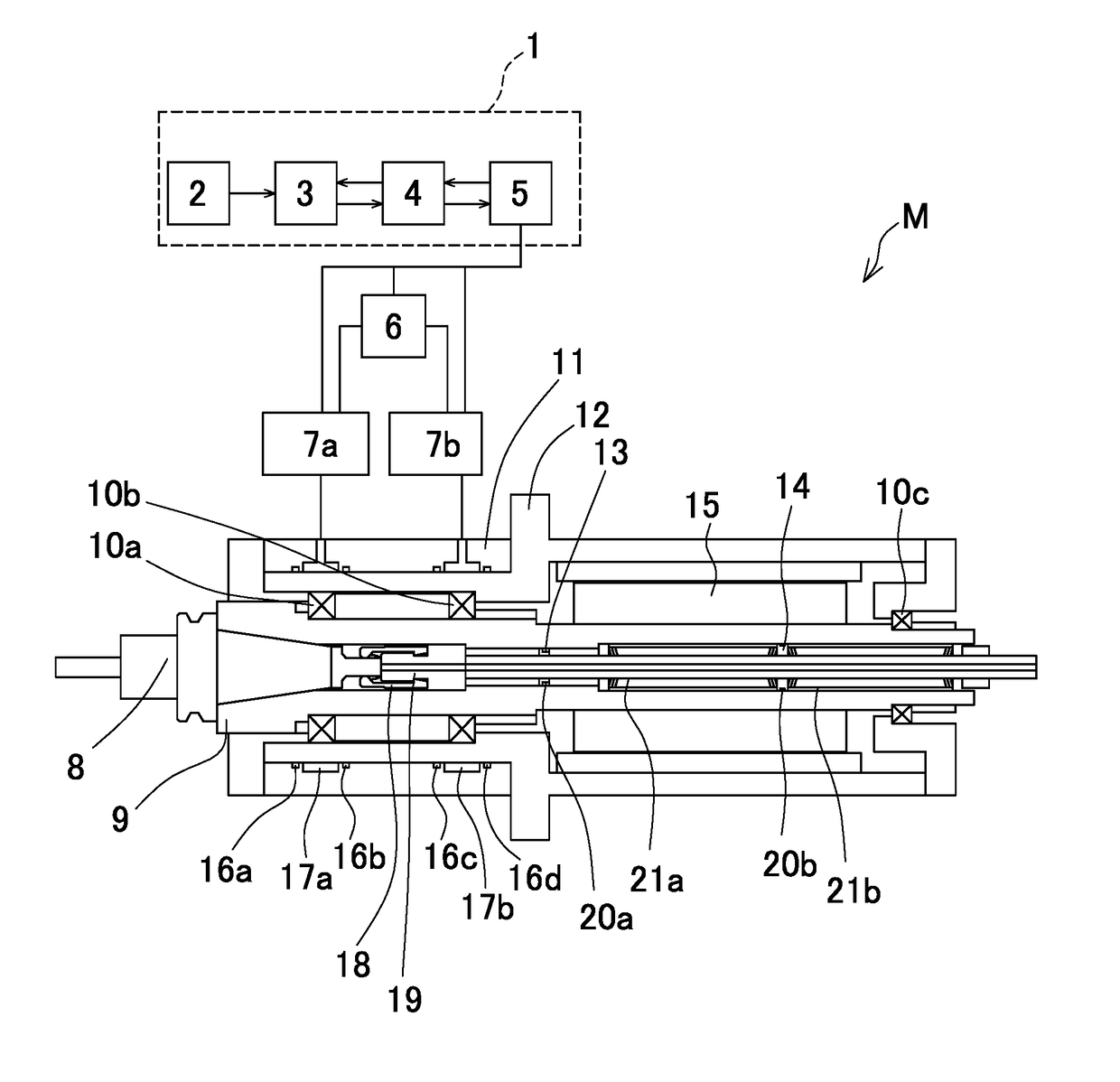
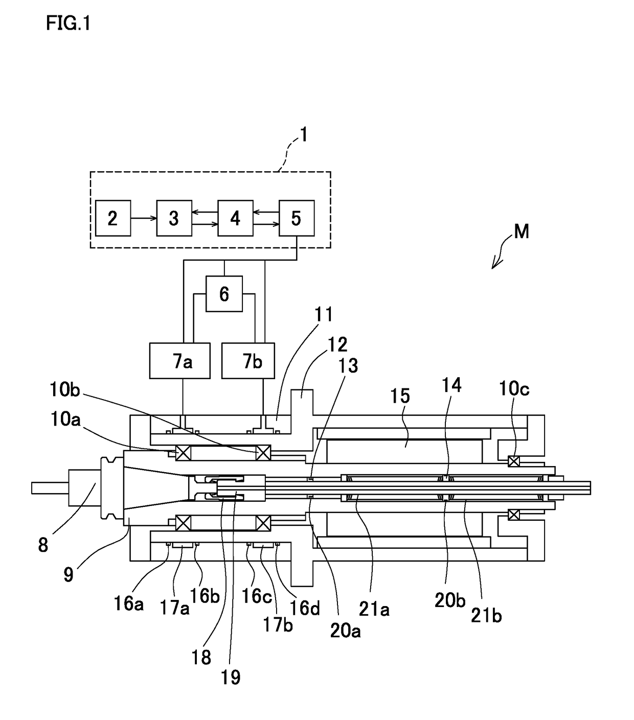
[0011]The following describes one embodiment of a main spindle device for a machine tool according to the disclosure based on the drawings in detail. FIG. 1 illustrates a main spindle device of a horizontal machining center, and a main spindle device M includes a main spindle 9, a housing 11, a sleeve 12, bearings 10a, 10b, and similar component.

[0012]A front part of the main spindle 9 is axially supported by the bearings (rolling bearings) 10a, 10b, and a rear part thereof is axially supported by a bearing (rolling bearing) 10c. The main spindle 9 extends in a front-rear direction (right-left direction in FIG. 1) of the machining center, and has a hollow cylindrical shape. Then, a collet 18, a drawbar 19, a plurality of disc springs 21, 21 . . . , and ring-shaped collars 13, 14 are inserted into an inside of the main spindle 9.

[0013]Cushioning members 20a, 20b are installed on outer peripheral surfaces of the collar 13 and the collar 14. Then, the collar 13 is embedded on a positio...


PUM

PropertyMeasurementUnit
vibration displacementaaaaaaaaaa
attenuation coefficientaaaaaaaaaa
rigidityaaaaaaaaaa

Abstract

A main spindle device for a machine tool includes a main spindle, a cushioning member, and an arithmetic unit. The cushioning member is disposed on a position where a vibration displacement of a rotator exists. The arithmetic unit uses data of a tool to be used to analyze a vibration mode in a free vibration of the rotator based on a support rigidity of a bearing, masses of respective parts of the rotator including the tool, an attenuation coefficient, and an equation of motion derived from rigidity and inertia by a rotation. An outer diameter of a sleeve positioned outside the bearing is changed such that a position of an antinode of the vibration or a position on which a vibration displacement exists in the vibration mode matches a position of the cushioning member inside the main spindle to change a preload on the bearing.

Description

BACKGROUND[0001]This application claims the benefit of Japanese Patent Application Number 2016-141640 filed on Jul. 19, 2016, the entirety of which is incorporated by reference.TECHNICAL FIELD[0002]The disclosure relates to a main spindle device for a machine tool.RELATED ART[0003]In a cutting processing using a machine tool, especially a machining center, vibrations occur due to various causes. Conventionally, Japanese Patent Application Publication No. 2012-171074 proposes a method that controls a rotation speed of a main spindle to reduce or avoid the vibration when the vibration occurs during a processing. Such method sometimes fails to reduce the vibration by simply changing the rotation speed when the vibration is caused by a natural frequency of a mechanical system. Therefore, Japanese Patent Application Publication No. 5-138408 discloses an attempt that, for avoiding the vibration caused by the natural frequency of the mechanical system, a rigidity of a bearing is increased ...

Claims


Application Information

Patent Timeline
Patent Type & Authority Applications(United States)
IPC IPC(8): B23Q11/00F16C27/04F16C19/52
CPCB23Q11/0039F16C19/527F16C27/045F16F2232/02F16C2233/00F16C2322/39F16F15/12F16C2229/00B23Q1/70F16F15/002F16F15/0235F16C25/06B23Q11/0032F16F2222/00
Inventor KOIKE, ISSEIKAWADA, NAOKI
Owner OKUMA CORP
Why Eureka
Try Eureka