

Semiconductor laser oscillator
a laser oscillator and semiconductor technology, applied in the direction of semiconductor laser arrangements, semiconductor lasers, manufacturing tools, etc., can solve the problems of low wavelength locking efficiency, inability to maximize the performance of the semiconductor laser oscillator, and increase the loss of lasers to be emitted, so as to achieve high wavelength locking efficiency
- Summary
- Abstract
- Description
- Claims
- Application Information
AI Technical Summary
Benefits of technology
Problems solved by technology
Method used
Image

Examples
first configuration example
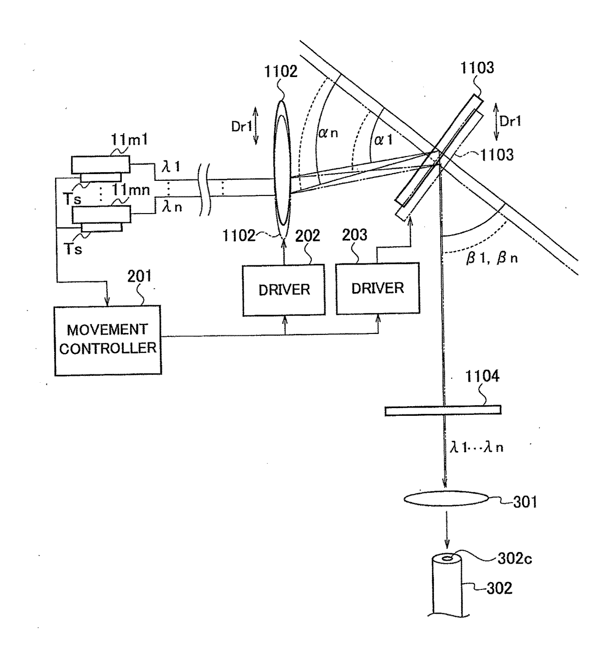
[0044]FIG. 4 shows the first configuration example. In FIG. 4, the same reference numerals are assigned to the same portions as those in FIG. 3. In FIG. 4, illustration of the optical fibers 11f1 to 11fn and the fiber unit 1101 in FIG. 3 is omitted.
[0045]As shown in FIG. 4, temperature sensors TS are individually attached to the laser diode modules 11m1 to 11mn. The temperature sensors TS may be incorporated on the insides of the laser diode modules 11m1 to 11mn. The temperature sensors TS may be attached to only one of the laser diode modules 11m1 to 11mn or a plurality of selected laser diode modules 11m.
[0046]A laser diode module 11m that does not compose the external resonator may be provided separately, and a wavelength of a laser emitted from such a separate laser diode module 11m may be monitored, whereby the temperatures of the laser diode modules 11m1 to 11mn may be indirectly detected (measured). Such measurement (estimation) of the temperature of the laser diode module 1...
second configuration example
[0066]FIG. 5 shows the second configuration example. In FIG. 5, the same reference numerals are assigned to the same portions as those in FIG. 3 and FIG. 4. In FIG. 5, an illustration of the optical fibers 11f1 to 11fn, the fiber unit 1101 and the collimating lens 1102 in FIG. 3 are omitted.
[0067]The configuration and operation of the second configuration example will be described focusing on the differences from the first configuration example. In the second configuration example, the collimating lens 1102 is fixed.
[0068]Temperature data of the laser diode module 11m, which is detected by the temperature sensor TS, is supplied to a rotation / movement controller 204. For example, the rotation / movement controller 204 can be composed of a microcomputer.
[0069]The grating 1103 is configured to be freely-rotatable. When the grating 1103 is rotated, the optical axis, along which the laser is emitted, is deviated. In the second configuration example, a total reflection mirror 1105, which is...
third configuration example
[0079]FIG. 6 shows the third configuration example. In FIG. 6, the same reference numerals are assigned to the same portions as those in FIG. 3 and FIG. 4. Also in FIG. 6, the illustration of the optical fibers 11f1 to 11fn and the fiber unit 1101 in FIG. 3 is omitted.
[0080]The configuration and operation of the third configuration example will be described focusing on differences from the first configuration example. In the third configuration example, the collimating lens 1102 and the grating 1103 are fixed. In the third configuration example, a synthetic quartz substrate 1106 is disposed in front of the collimating lens 1102, that is, between the fiber unit 1101 (not shown) and the collimating lens 1102. The synthetic quartz substrate 1106 is artificially manufactured quartz glass.
[0081]Temperature data of the laser diode module 11m, which is detected by the temperature sensor TS, is supplied to a rotation controller 207. The rotation controller 207 can be composed of a microcomp...
PUM
| Property | Measurement | Unit |
|---|---|---|
| Temperature | aaaaa | aaaaa |
| Angle | aaaaa | aaaaa |
Abstract
Description
Claims
Application Information