Laser scanning device and laser scanning system

a laser scanning and laser scanning technology, applied in the field of laser marking, can solve the problems of hardly achieving a better control effect, inability to maximize the system effect, and instruction transmission error, so as to improve the reliability of the system, simplify the whole laser scanning device, and improve the effect of real-tim

Active Publication Date: 2018-02-01
HANS LASER TECH IND GRP CO LTD +1
View PDF0 Cites 2 Cited by
  • Summary
  • Abstract
  • Description
  • Claims
  • Application Information

AI Technical Summary

Benefits of technology

[0004]Accordingly, it is necessary to provide a laser scanning device, which can reduce crosstalk of signal and instruction transmission error.
[0022]The above laser scanning device and scanning system can integrate a laser control function and a galvanometer control function into the same chip by a system on chip design, which simplifies the whole laser scanning device, greatly reduces cost of the system, and improves reliability of the system. Because all information are transmitted in the same one chip, there is no signal transmission cable employed between a conventional movement control card and a galvanometer driver, which results in a better real time, and avoids various problems due to transmission from the conventional control card to the galvanometer, such as crosstalk of signal and instruction transmission error.
[0023]Because the galvanometer movement instruction generation and the servo control are implemented in the same chip, communication between the galvanometer movement instruction generation and the servo control is not limited, which can implement the control algorithm of more complexity and high performance.

Problems solved by technology

This solution can result in problems such as crosstalk, instruction transmission error and the like in the practical application due to the transmission cable between the movement control card 202 and the galvanometer driver 204.
Further, due to data unidirectional transmission, the system status, particularly the status of the galvanometer 205, cannot be obtained by the movement control card 202, and then the laser is controlled by a manner of open loop, which hardly achieves a better control effect.
Particularly, in some occasions of a high performance requirement, the conventional solution generally achieves a certain scanning effect at the cost of efficiency, which cannot maximize the system effect.

Method used


Image

  • Laser scanning device and laser scanning system
  • Laser scanning device and laser scanning system
  • Laser scanning device and laser scanning system

Examples


Embodiment Construction

[0027]The present invention will be described in the following with reference to the accompanying drawings and the embodiments.

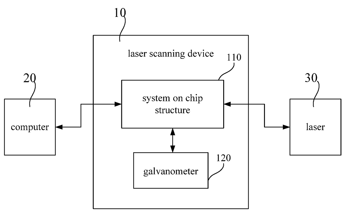
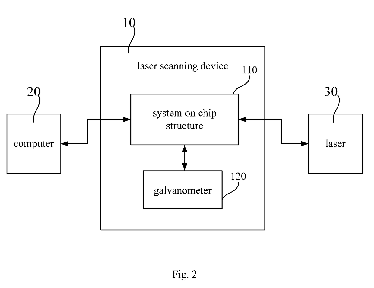
[0028]FIG. 2 is a block diagram of a laser scanning device in an embodiment. The laser scanning device 10 is also called a laser square head, which can be configured to receive a graphic data transmitted by an external computer 20 and control light emitting of the laser 30 to form a laser pattern on a workpiece. Data is transmitted between the laser scanning device 10 and the external computer 20 through a high speed data channel, such as an Ethernet interface, a USB interface or a 1394 interface.

[0029]The laser scanning device 10 includes a system on chip structure 110 and a galvanometer 120. The system on chip structure 110 is configured to receive and process a graphic data transmitted by an external computer 20 to generate a galvanometer movement instruction and a laser control instruction. The galvanometer 120 receives the galvanometer movement instruct...


PUM

PropertyMeasurementUnit
drive voltageaaaaaaaaaa
movementaaaaaaaaaa
speedaaaaaaaaaa

Abstract

A laser scanning device (10), comprising: a system on chip structure (110) configured to receive and process a graphic data transmitted by an external computer (20) to generate a galvanometer movement instruction and a laser control instruction; and galvanometer (120) configured to receive the galvanometer movement instruction and move according to the galvanometer movement instruction; wherein the laser control instruction is transmitted to an external laser (30), so that the laser (30) and the galvanometer (120) move synchronously. The above laser scanning device (10) and scanning system can integrate a laser control function and a galvanometer control function into the same chip by a system on chip design, which does not only reduce cost of the system, but also improve reliability of the system. Because all information are transmitted in the same one chip, there is no signal transmission cable employed between a conventional movement control card and a galvanometer driver, which results in a better real time, and avoids various problems due to transmission from the conventional control card to the galvanometer.

Description

FIELD OF THE INVENTION[0001]The present invention relates to a technical field of a laser marking, and particularly relates to a laser scanning device and a laser scanning system.BACKGROUND OF THE INVENTION[0002]FIG. 1 is a block diagram of a conventional laser scanning control system. The laser scanning control system includes a computer 201, a movement control card 202, a laser and a scanning head 206. The scanning head 206 includes a galvanometer driver 204 and a galvanometer 205. As shown in FIG. 1, the conventional laser scanning control system uses the solution that the movement control card 202 and the galvanometer driver 204 are separated. In other words, the movement control card 202 control light emitting of the laser and generate a galvanometer instruction; the galvanometer driver 204 drives the galvanometer 205 to move according to a given track. This solution can result in problems such as crosstalk, instruction transmission error and the like in the practical applicati...

Claims


Application Information

Patent Timeline
Patent Type & Authority Applications(United States)
IPC IPC(8): G02B26/10H04N9/31
CPCG02B26/101H04N9/3135B23K26/082
Inventor WANG, GUANGNENGQIN, HONGYANLI, YUTINGZHANG, GUOPINGDING, BINGGAO, YUNFENG
Owner HANS LASER TECH IND GRP CO LTD
Why Eureka
Try Eureka