Encoder signal processing device, encoder, and signal processing method and recording medium

a signal processing device and encoder technology, applied in the direction of coding, error coding/decoding sychronisation, instruments, etc., can solve the problem of difficult to eliminate detection errors, and achieve the effect of suppressing variation in acceleration components

Active Publication Date: 2018-02-08
FANUC LTD
View PDF0 Cites 8 Cited by
  • Summary
  • Abstract
  • Description
  • Claims
  • Application Information

AI Technical Summary

Benefits of technology

[0015]According to the present invention, it is possible to suppress a variation in an acceleration compone

Problems solved by technology

In the technique disclosed in Patent Document 2, since correction is performed according to position data within one rotation o

Method used


Image

  • Encoder signal processing device, encoder, and signal processing method and recording medium
  • Encoder signal processing device, encoder, and signal processing method and recording medium
  • Encoder signal processing device, encoder, and signal processing method and recording medium

Examples


first embodiment

[Configuration]

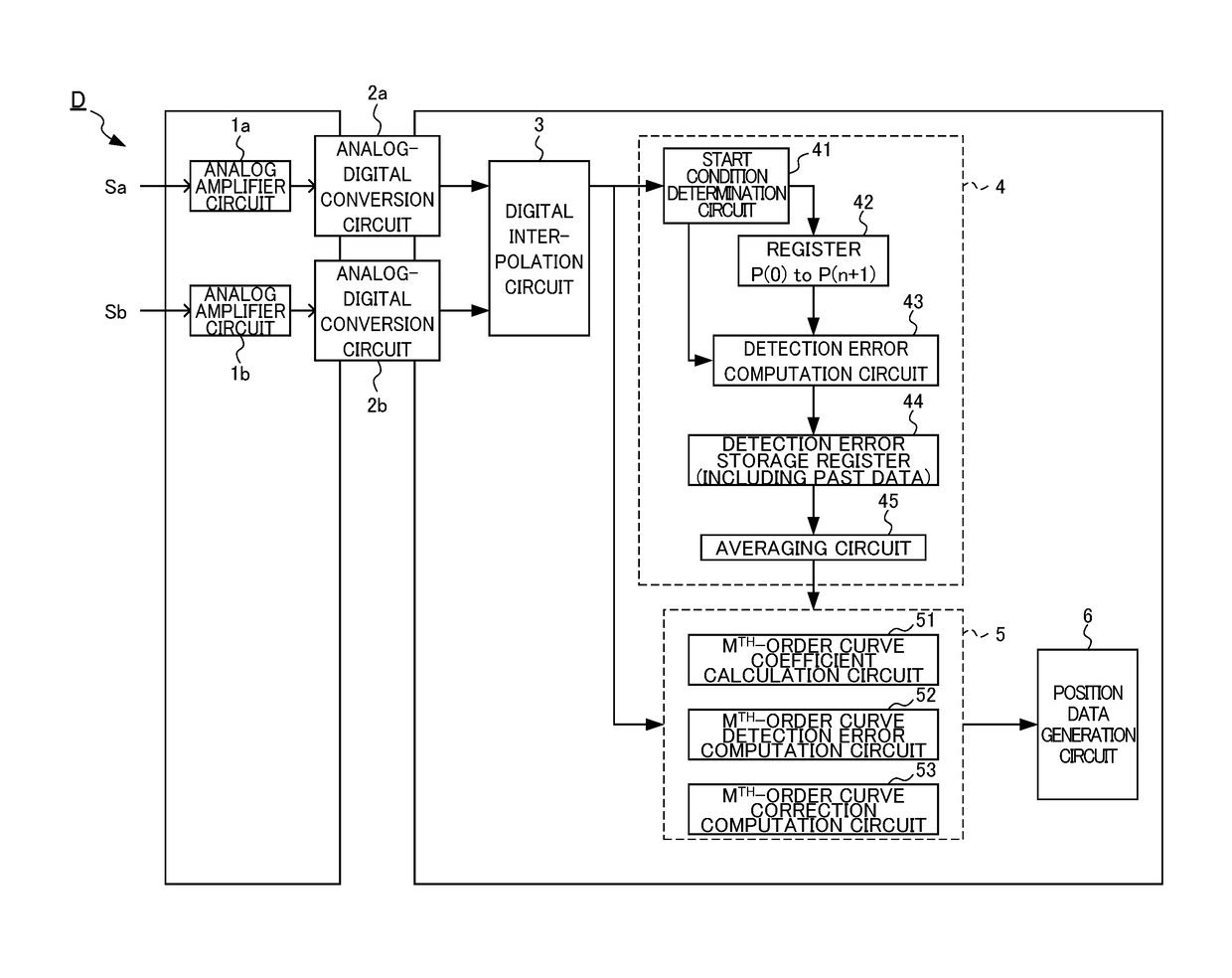
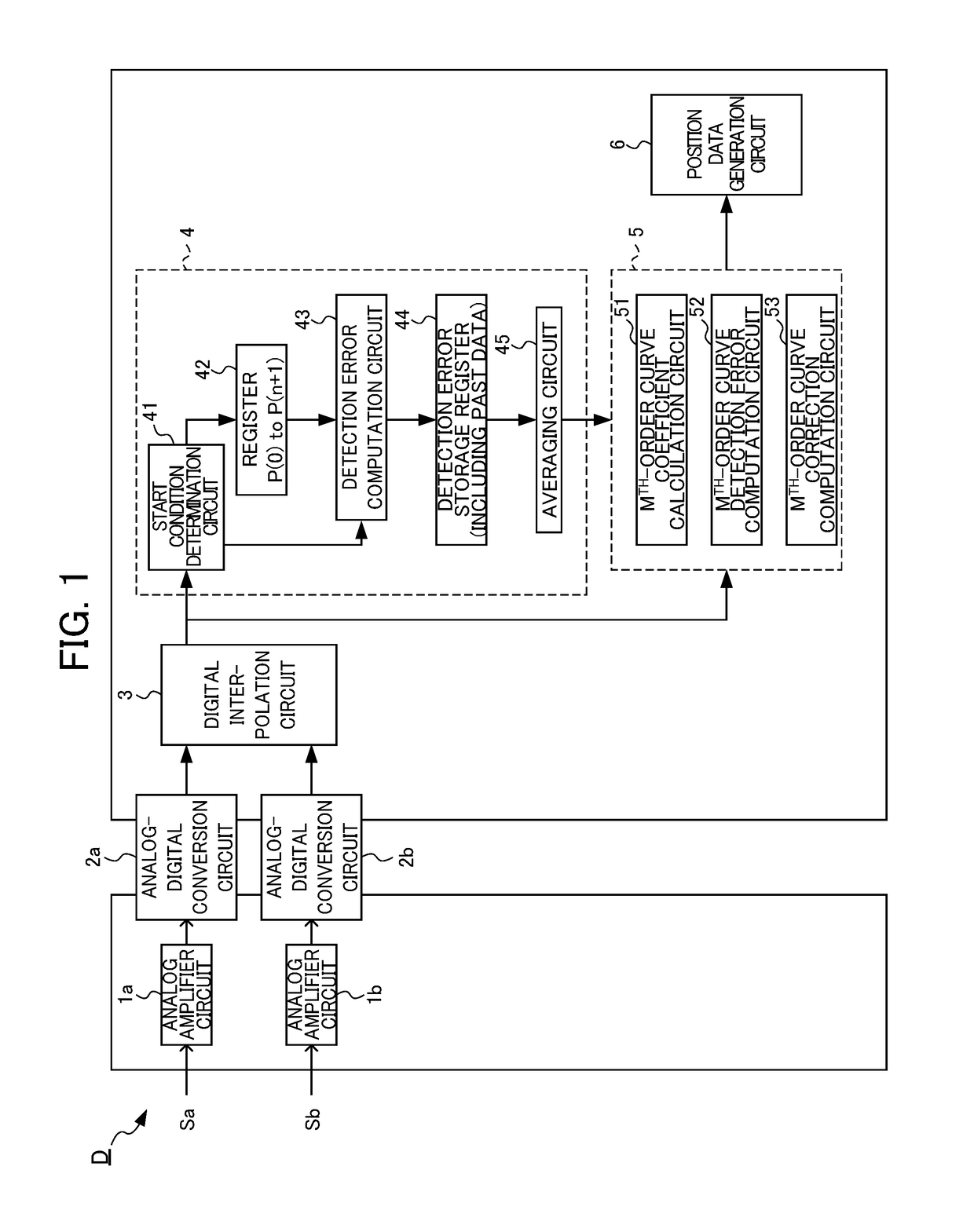
[0034]FIG. 1 is a block diagram illustrating a configuration of an encoder signal processing device D according to an embodiment of the present invention. In the present embodiment, analog amplifier circuits 1a and 1b amplify original signals of a sine wave Sa and a cosine wave Sb output from a sensing unit of an encoder according to movement of a measurement target so as to be appropriate to be input to analog-digital conversion circuits 2a and 2b on the next stage, respectively. The analog-digital conversion circuits 2a and 2b convert the amplified analog signals to digital signals at every predetermined sampling cycle. A digital interpolation circuit 3 computes the position within one cycle of the original signal (one cycle of the sine wave) on the basis of the converted digital value and outputs the computed position to a detection error data calculation circuit 4.

[0035]The detection error data calculation circuit 4 includes a start condition determination circuit...

second embodiment

[0055]Next, a second embodiment of the present invention will be described. In the second embodiment, the order of the approximate curve illustrated in the first embodiment is set to an odd-number order in order to be able to correct position data appropriately even when an encoder rotates in a backward direction.

[0056]FIG. 11 is a schematic diagram illustrating detection points used for calculation of coefficients for forward and backward rotation when the order of an approximate curve is an odd-number order (in this example, a third order). The detection positions for forward rotation in FIG. 6 and the detection positions for backward rotation are bilaterally reversed. As illustrated in FIG. 11, when the order of an approximate curve is a third order, it is possible to calculate the coefficients A, B, C, and D of the third-order curve using four detection points each located before and after a target time point tX and to calculate a detection error P(tX) at an arbitrary time point...

third embodiment

[0059]Next, a third embodiment of the present invention will be described. In the third embodiment, in order to simplify computation of a detection error and to accelerate processing, a predetermined detection error of an approximate curve is calculated and stored in advance. FIG. 13 is a schematic diagram illustrating a configuration of the Mth-order curve detection error computation circuit 52 according to the present embodiment. Moreover, FIG. 14 is a schematic diagram illustrating how, in an Mth-order curve that passes through the detection points, a detection error at a time point when detection points were evenly divided is calculated in advance.

[0060]As illustrated in FIG. 13, the Mth-order curve detection error computation circuit 52 of the present embodiment includes a register 52a and can store a predetermined calculated detection error in the register 52a. As illustrated in FIG. 14, the Mth-order curve detection error computation circuit 52 calculates in advance a detecti...


PUM


Abstract

An encoder signal processing device detects position data at every predetermined time interval from an original signal which is an analog amount generated in an encoder according to movement of a measurement target. The encoder signal processing device includes: an approximate curve calculation unit that calculates an approximate curve of a detection error included in the original signal on the basis of the detection error of the position data at at least three or more points; an approximate error computation unit that computes an approximate value of the detection error of the position data at an arbitrary time point on the basis of the approximate curve of the detection error; and a position data correction unit that corrects the detection error of the position data at the arbitrary time point on the basis of the approximate value of the detection error of the position data.

Description

[0001]This application is based on and claims the benefit of priority from Japanese Patent Application No. 2016-153817, filed on 4 Aug. 2016, the content of which is incorporated herein by reference.BACKGROUND OF THE INVENTIONField of the Invention[0002]The present invention relates to an encoder signal processing device, an encoder, and a signal processing method and recording medium.Related Art[0003]Conventionally, it is known that an encoder has a detection error which occurs in synchronization with one cycle of an original signal. This detection error occurs since the original signal is not ideal sine and cosine waves but includes an offset voltage, an amplitude difference, a phase difference, a waveform distortion, and the like. When an output signal of an encoder includes a detection error, detection accuracy of the position of a measurement target decreases. In order to correct such a detection error, according to a technique disclosed in Patent Document 1, an error amount is...

Claims


Application Information

Patent Timeline
IPC IPC(8): H03M13/33H03M13/00
CPCH03M13/615H03M13/33G01D5/2449G01D5/24495G01D5/00
Inventor KONDOU, YOUHEI
Owner FANUC LTD
Why Eureka
Try Eureka