Compact exchanger for indirect-injection cyrogenic transportation

a technology of indirect injection and cyrogenic transportation, which is applied in the direction of tubular elements, lighting and heating apparatus, stationary conduit assemblies, etc., can solve the problems of inconvenient use of standard exchangers/evaporators for cryogenic liquid, the choice of exchanger technology employed, and the use of cryogenic liquid as cryogenic liquid remains very serious, so as to achieve the effect of improving compactness and ease of assembly and notable performan

Active Publication Date: 2018-02-15
LAIR LIQUIDE SA POUR LETUDE & LEXPLOITATION DES PROCEDES GEORGES CLAUDE
View PDF7 Cites 2 Cited by
  • Summary
  • Abstract
  • Description
  • Claims
  • Application Information

AI Technical Summary

Benefits of technology

[0014]The present invention therefore aims to propose an innovative cryogen/air ((nitrogen, oxygen, argon, krypton, . . . or mixtures thereof)/air) exchanger design intended for the refrigerated transportation application enabl

Problems solved by technology

However, there remains a difficulty, namely the choice of the exchanger technology employed in the load space: its design and its installation are crucial in arriving at a solution offering good performance and addressing the specifications of this industrial sector.
These standard exchangers/eva

Method used


Image

  • Compact exchanger for indirect-injection cyrogenic transportation
  • Compact exchanger for indirect-injection cyrogenic transportation
  • Compact exchanger for indirect-injection cyrogenic transportation

Examples


Embodiment Construction

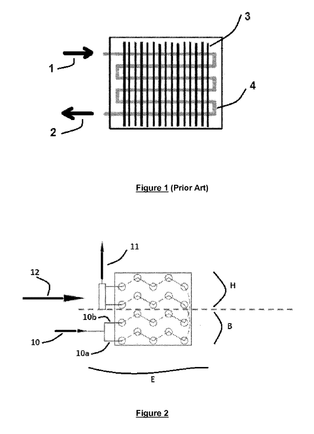
[0042]As stated above FIG. 1 is a diagrammatic side view of part of a prior art tube and fin bundle that includes a system of plane, continuous and parallel fins (3) through which a single duct (4) passes inside the exchanger (cryogen inlet at 1, cryogen outlet at 2), air circulating inside the exchanger through channels defined by the space between the duct and the parallel fins, and in this instance the air circulates in a direction that here is perpendicular to the plane of the figure (resulting in so-called “crossed-flow” exchanger).

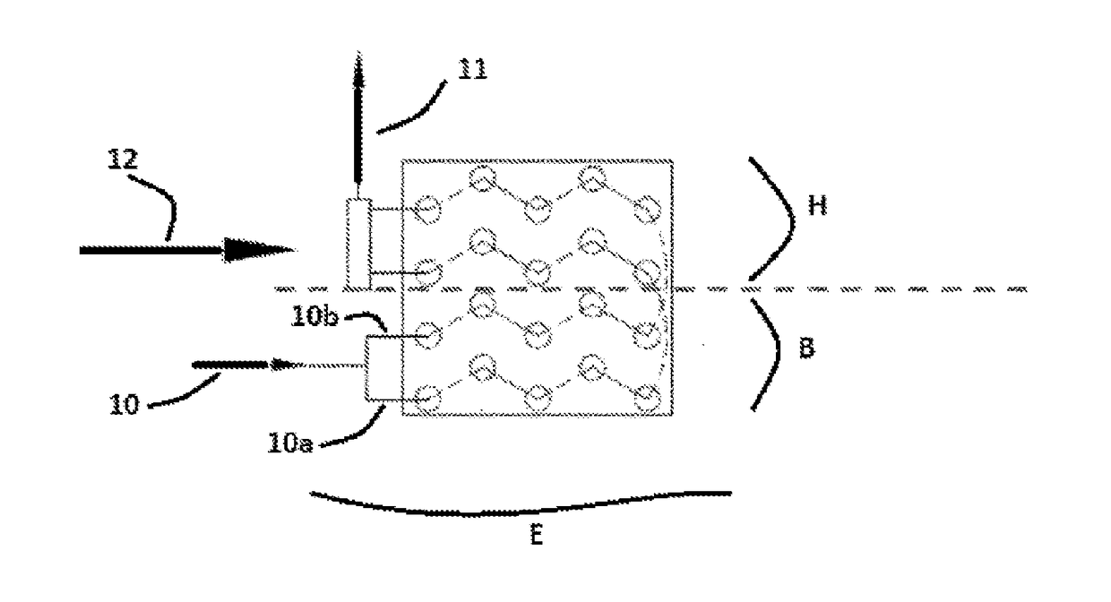
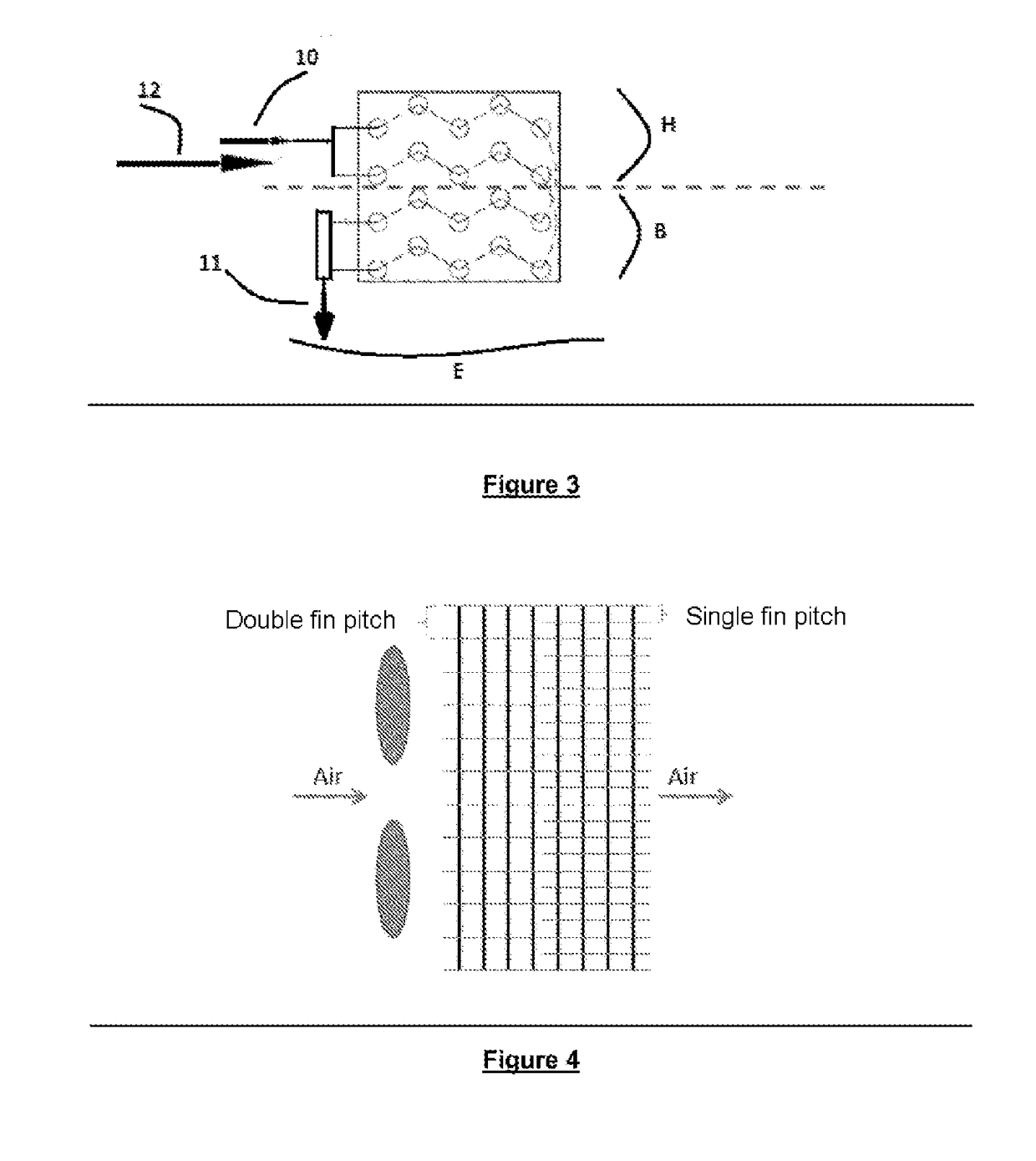
[0043]On the other hand, FIG. 2 shows an exchanger structure according to the invention using in a bottom inlet configuration:[0044]references 10 and 11 respectively designate the inlet of the cryogen into the exchanger and the outlet of the cryogen from the exchanger.[0045]the exchanger is characterized by the presence of two independent ducts 10a and 10b forming the cryogen circuit inside the exchanger.[0046]reference 12 for its part designates the...


PUM


Abstract

Exchanger having a tube and fin bundle and comprising: a duct (4) through which a cryogenic fluid can flow between a fluid inlet (1) into the exchanger and a fluid outlet (2) from the exchanger; and a system of flat, continuous and parallel fins (3) through which said duct passes inside the exchanger, it being possible for air (12) to circulate within the exchanger by passing through channels delimited by the space between the duct and the parallel fins. The exchanger is characterized in that it comprises at least two independent ducts (10a, 10b) for the circulation of cryogenic fluid within the exchanger.

Description

CROSS-REFERENCE TO RELATED APPLICATIONS[0001]This application is a § 371 of International PCT Application PCT / FR2015 / 053105, filed November 17, 2015, which claims § 119(a) foreign priority to French patent application FR 1 461 237, filed Nov. 20, 2014.BACKGROUNDField of the Invention[0002]The present invention concerns the field of the transportation and distribution of heat-sensitive products such as pharmaceutical products and foodstuffs. In this field, the refrigeration necessary for maintaining the temperature of the products is mainly provided by two different technologies:[0003]a closed loop mechanical vapor compression refrigeration unit; or[0004]an open loop cryogenic unit employing direct or indirect injection of cryogenic fluids and in particular liquid nitrogen.[0005]The present invention more particularly concerns indirect-injection cryogenic solutions. In solutions of this kind, the cryogenic fluid is fed from a cryogenic reservoir onboard the refrigerated truck (genera...

Claims


Application Information

Patent Timeline
IPC IPC(8): B60H1/32F28F1/32F25B39/02F28D1/047F25D3/10B60H1/00F28D1/04
CPCB60H1/3227B60H1/00335B60H1/00014F28F1/32F28D1/0417F28D1/0477F25D3/10F25B39/02F28D2021/0033F28D2021/0064
Inventor YOUBI-IDRISSI, MOHAMMEDDALLAIS, ANTONYCLEMENT, CECILEZERBINATTI, CELSO
Owner LAIR LIQUIDE SA POUR LETUDE & LEXPLOITATION DES PROCEDES GEORGES CLAUDE
Why Eureka
Try Eureka