
Methods of forming rotary sputtering target

a technology of rotary sputtering and target, which is applied in the direction of cobalt compounds, manufacturing tools, solventing apparatus, etc., can solve the problems of generating significant limitations for the use of inductive heating, and achieve the effects of avoiding surface polishing, excellent bonding quality, and fast final cleaning

Active Publication Date: 2018-02-22
XIANDAO THIN FILM MATERIALS GUANGDONG CO LTD
View PDF0 Cites 5 Cited by
  • Summary
  • Abstract
  • Description
  • Claims
  • Application Information

AI Technical Summary

Benefits of technology

The present invention provides methods for protecting target bodies during an induction heating process and ensuring a uniform cooling of the components. These methods involve using a protective wrap to prevent adhesion deposits and a conductive wrap for use with an induction heater. Additionally, a combination of both a protective wrap and a conductive wrap can be used for target bonding. These methods may be useful for ensuring the proper functioning and reliability of the target body during use.

Problems solved by technology

This normally would be perceived as generating significant limitations for the use of inductive heating in target bonding shops where a variety of cylindrical ceramic materials might be involved, some with physical properties that render them generally unsusceptible to direct inductive heating.

Method used


Image

  • Methods of forming rotary sputtering target
  • Methods of forming rotary sputtering target
  • Methods of forming rotary sputtering target

Examples


embodiment 1

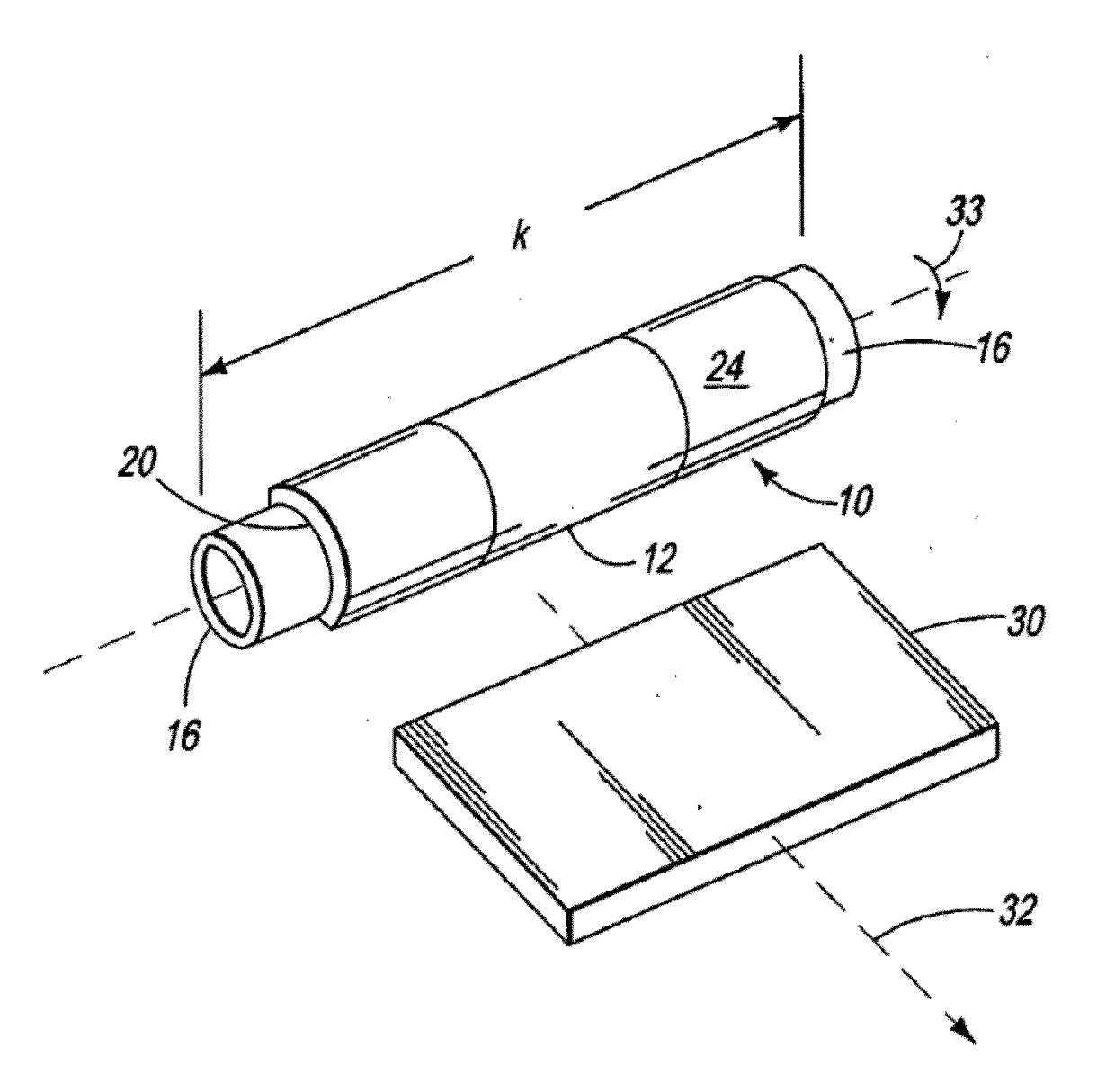
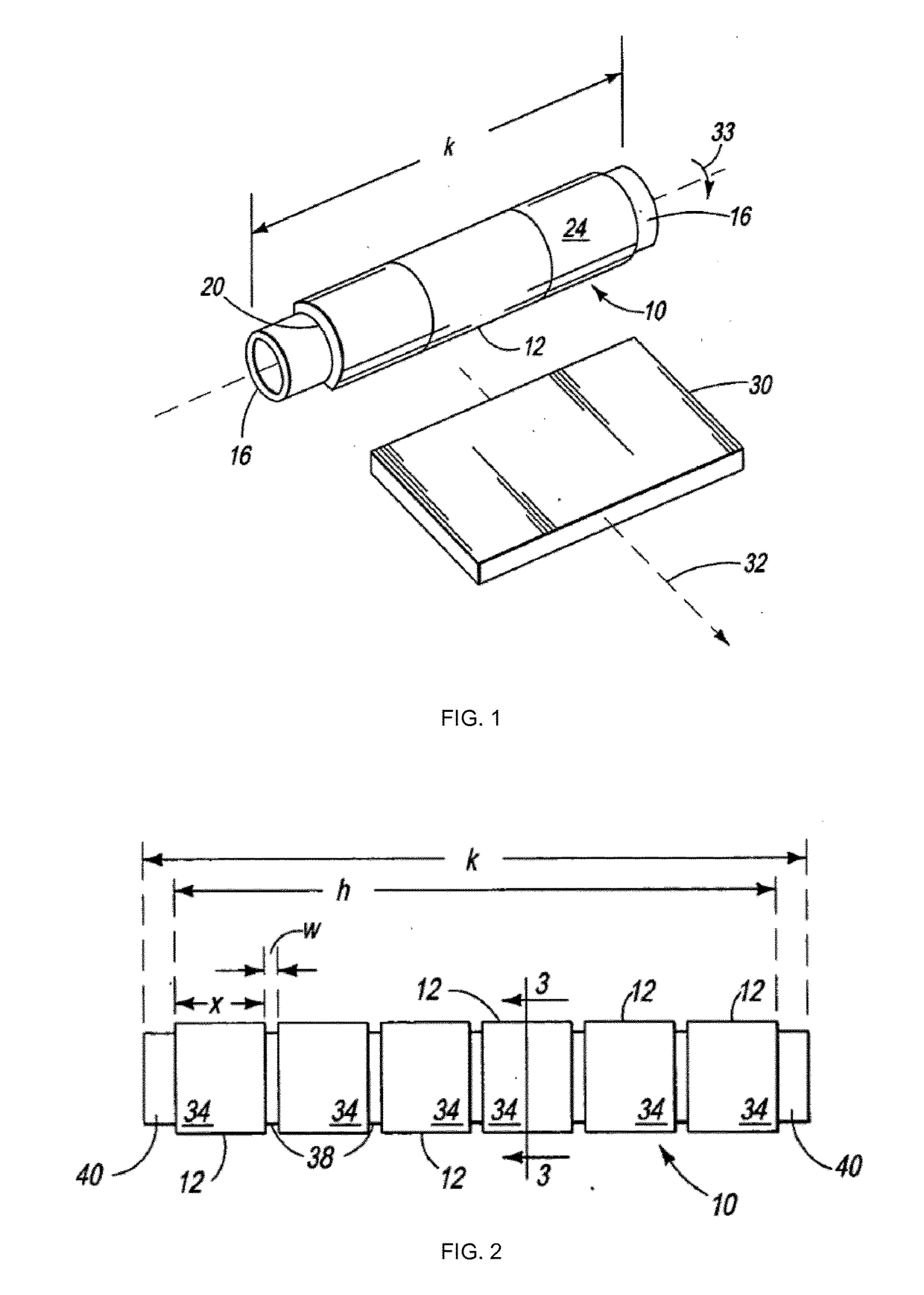
[0064]A first process of forming a rotary sputtering target comprising the steps of:[0065]providing a heat-conductive (and preferably electrically conductive) material-based backing tube having an outer diameter and an outer diameter surface that is defined around a (central) longitudinal axis of the backing tube;[0066]providing a first hollow cylindrical target body having a (central) longitudinal axis defined between two edges of the first body, said edges (bottom and top edges) being opposed to each other, an inner diameter, an inner diameter surface, an outer diameter, and an outer diameter surface, said inner diameter surface and outer diameter surface being defined around the longitudinal axis of the first hollow cylindrical target body, said first hollow cylindrical target body consisting of—or comprising an electrically conductive material and thereby being an electrically conductor body;[0067]providing (at least) one induction heater having an inner diameter;[0068]at least ...

embodiment 2

[0087]The first process of forming a rotary sputtering target comprising an additional step of:[0088]at least partially, preferably fully, covering the outer diameter surface of the first hollow cylindrical target body with a first protective material removably (i.e. on the basis of a non-permanent way) connected to said outer diameter surface of the first hollow cylindrical target body, said step of at least partially covering of the outer diameter surface of the first hollow cylindrical target being performed before the step of filling the first gap with a soldering material, preferably, the step of at least partially covering of the outer diameter surface of the first hollow cylindrical target body by said first protective material is performed before the step of coating the inner diameter surface of the first hollow cylindrical target body with a soldering material.

[0089]Optionally, in embodiment 2, the first protective material is a protective film or a protective wrap.

[0090]In...

embodiment 3

[0097]The first process of forming a rotary sputtering target, wherein the backing tube is rotated and / or oscillated along its longitudinal axis during the pre-heating step and / or the heating step.


PUM

PropertyMeasurementUnit
Temperatureaaaaaaaaaa

Abstract

A sputtering target assembly formed by relative positioning of a sputtering target body or bodies and a backing support, such that the backing support is placed within the inside diameter of the sputtering target body. The combination is heated with an induction heater surrounding the target body so that there is achieved a suitable temperature for bonding. Heating is discontinued such that there is a cooling of the bonding material and a bonding relationship established between the sputtering target body (or bodies) and the backing support. Embodiments include adding a conductive layer, as in a conductive fabric wrap, between the induction heater and internal target body(ies) that is / are inductively heated in a manner that enhances axial and radial gradient heating during bonding. The conductive wrap can be used with a low conductivity material as in an LiMO2 (e.g., Li—CoO2) target body. A non-adhesive protective wrap can also be placed about the target body such as between the conductive wrap and target body.

Description

FIELD OF THE INVENTION[0001]The present invention relates to methods of producing rotary sputtering target assemblies and rotary sputtering target assemblies produced with such methods.BACKGROUND OF THE INVENTION[0002]Sputtering target assemblies are used in the formation of a wide variety of products. Some typical substrates on which the target material of sputtering target assemblies is deposited include items such as semiconductor devices, compact discs (CDs), hard disks for use in magnetic disk drives, solar cells, optical devices such as flat panel displays, and non-aqueous lithium secondary batteries.[0003]A typical sputtering apparatus, such as one used in the production of the above described items, comprises a vacuum chamber inside of which are positioned the sputtering target assembly and the substrate. The target of the target assembly is electrically configured to be an electrode with a large ion flux. An inert gas, often in conjunction with a reactive gas, is introduced...

Claims


Application Information

Patent Timeline
IPC IPC(8): C23C14/34H01J37/34B23K1/002
CPCC23C14/3414H01J37/3491B23K1/002Y02E60/10C23C14/3407C01G51/42C04B35/01C04B35/6261C04B35/63C04B35/62695C01P2004/53C04B2235/602C04B2235/612C04B2235/77C04B2235/3275C04B2235/5436H01J37/342H01J37/3426B22F3/04
Inventor SHIN, JONG-WONMARGADANT, NIKOLAUS
Owner XIANDAO THIN FILM MATERIALS GUANGDONG CO LTD
Learn More