Device and method for nanoparticle sizing based on time-resolved on-chip microscopy

a nanoparticle and microscopy technology, applied in the field of nanoparticles, can solve the problems of large capital investment, slow image acquisition, and inability to cover a large dynamic range of particle sizes and concentrations within a field-portable, cost-effective and rapid interfa

Inactive Publication Date: 2018-02-22
RGT UNIV OF CALIFORNIA
View PDF5 Cites 39 Cited by
  • Summary
  • Abstract
  • Description
  • Claims
  • Application Information

AI Technical Summary

Benefits of technology

[0010]In one embodiment, a device for the imaging and sizing of objects incorporates tunable vapor condensation of nanolenses and time-resolved lens-free holographic imaging in a single portable, hand-held device. Using this portable device and the reconstructed, time-resolved, and automatically-focused phase images of the sample field-of-view, platform is able to count and size nanometer-sized objects. The platform works with larger particle sizes as well (e.g., millimeter sized objects). Compared to other nanoparticle sizing approaches in general, the lens-free holographic imaging and vapor condensation platform provides highly advantageous features including: label-free protocols, an ultra-large particle sizing range (˜40 nm to millimeter-scale), an imaging-based approach that provides particle localization in addition to sizing information, field-portability, cost-effectiveness, and a large field of view that can handle a wide range of particle concentrations (spanning up to 6 orders of magnitude), as well as the potential to achieve spatially multiplexed detection and sizing of different target nanometer-sized particles over a large area by patterning different capture zones.

Problems solved by technology

While there are various nanoparticle detection and sizing methods, there is a lack of high-throughput instruments that can cover a large dynamic range of particle sizes and concentrations within a field-portable, cost-effective and rapid interface.
Existing non-optical methods, such as transmission electron microscopy (TEM), scanning electron microscopy (SEM), and atomic force microscopy, are typically very accurate and provide a gold standard for particle sizing; however they are bulky, require significant capital investment, can be slow in image acquisition, and provide extremely restricted fields of view (FOVs) that limit throughput for particle sizing.
Optical techniques can be more cost-effective and rapid, however it is in general difficult to overcome the challenge of obtaining a large enough signal-to-noise (SNR) ratio to detect and reliably size both individual nanoparticles and populations of nanoparticles.
Although these techniques can provide accurate sizing data, they too suffer from many of the drawbacks of the non-optical methods: bulkiness, capital cost, relatively slow imaging speed as well as significantly restricted FOVs, which limit the sizing throughput.
Because it is a statistical method, DLS only provides collective sizing data about particles' hydrodynamic diameters, without providing sizing information on an individual particle-by-particle basis.
As a result of this, DLS has limited accuracy for poly-disperse samples with size heterogeneity, and in particular has difficulty resolving bimodal (or multi-modal) distributions where the modal means are either too closely spaced or too far apart.
However, both DLS and NTA tend to rely on bulky equipment, are limited in the range of particle concentrations they can handle (e.g., too much dilution results in low signal, while high density results in high noise due to multiple scattering events), and require sufficiently small particles (less than a few microns in diameter) such that the Brownian motion is noticeable, which limits the dynamic range of particle sizes that can be probed with these techniques.
However, because scattered intensity scales with the sixth power of a nanoparticle's diameter, it is difficult for this approach to detect particles smaller than ˜100 nm.
This approach effectively increases the particles' sizes, making them easier to detect, although sizing accuracy may be compromised due to differing condensation rates around particles of different sizes.
Nonetheless, low SNR remains a challenge for detecting and sizing particularly small particles, and holographic imaging has historically been used for particle sizing at the micro-scale, generally in conjunction with large bulky laboratory equipment, such as laboratory grade optical microscopes with relatively expensive objective lenses.
Recently, it has been shown that different methods of generating self-assembled nanolenses allow one to detect, using on-chip holographic imaging, particles as small as ˜40 nm; however this is without sizing capability.

Method used


Image

  • Device and method for nanoparticle sizing based on time-resolved on-chip microscopy
  • Device and method for nanoparticle sizing based on time-resolved on-chip microscopy
  • Device and method for nanoparticle sizing based on time-resolved on-chip microscopy

Examples


Embodiment Construction

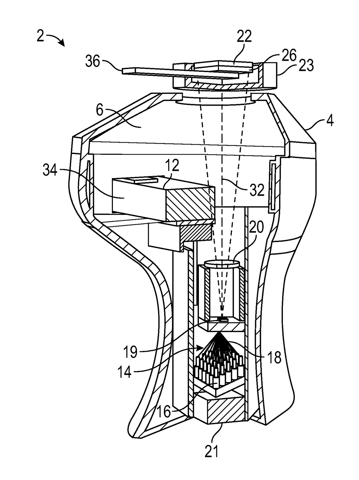
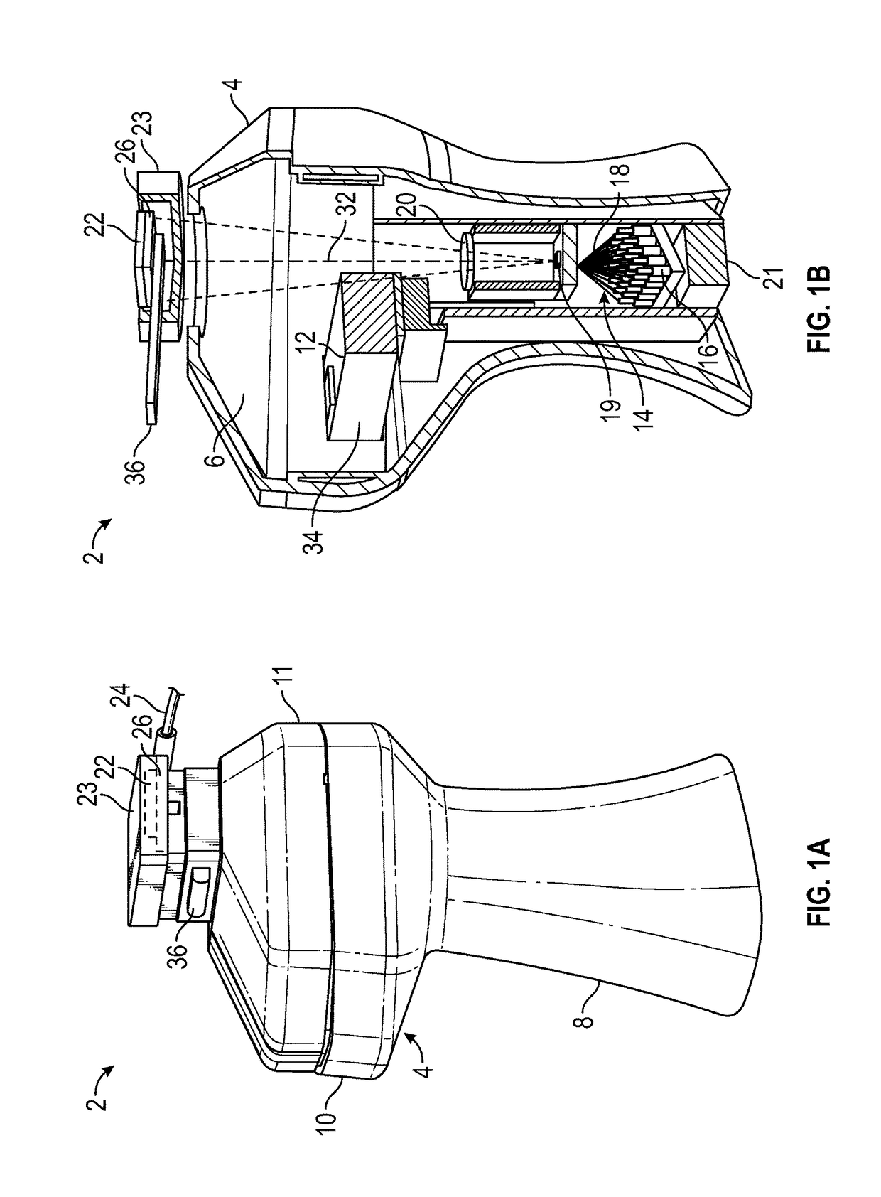
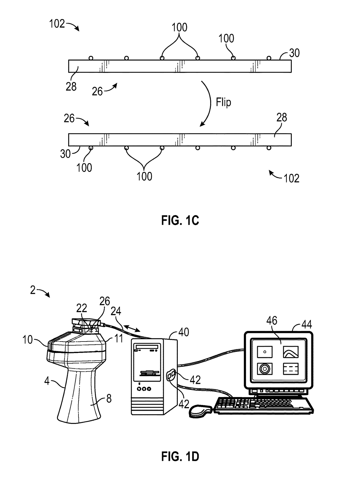
[0034]FIG. 1A illustrates a device 2 for the imaging and sizing of small objects 100 (FIG. 1C) within a sample. As described herein, the terms object or objects includes small sized objects such as particles that range from nanometer sized particles (e.g., those less than about 100 nm) up to larger sized particles (e.g., millimeter scale). The device 2 includes a housing 4 that includes an interior volume 6 (seen in FIG. 1B) therein that houses the various components of the device 2. The housing 4 is relatively small and is hand-held and portable. The housing 4 may include a grip portion 8 that is ergonomically designed so that the hand of the user can readily grip and hold the device 2. As illustrated in FIGS. 1A and 1B, an upper region 10 of the housing 4 above the grip portion extends outwardly. The upper region 10 of the housing 4 may be opened whereby the upper region 10 includes an upper cap 11 portion that can be removed from the lower portion which allows for the loading of ...


PUM


Abstract

A method for the label-free sizing of small, nanometer-sized objects such as particles includes a hand-held, portable holographic microscope that incorporates vapor condensation of nanolenses and time-resolved lens-free imaging. The portable device is used to generate reconstructed, time-resolved, and automatically-focused phase images of the sample field-of-view. The peak phase value for each object a function of working distance (z2) and condensation time (t) is used to measure object size. The sizing accuracy has been quantified in both monodisperse and heterogeneous particle solutions, achieving an accuracy of + / −11 nm for particles that range from 40 nm up to 500 nm. For larger particles, the technique still works while the accuracy roughly scales with particle size.

Description

RELATED APPLICATION[0001]This Application claims priority to U.S. Provisional Patent Application No. 62 / 106,614 filed on Jan. 22, 2015, which is hereby incorporated by reference in its entirety. Priority is claimed pursuant to 35 U.S.C. §119 and any other applicable statute.STATEMENT REGARDING FEDERALLY SPONSORED RESEARCH AND DEVELOPMENT[0002]This invention was made with Government support under W911NF-13-1-0419, awarded by the U.S. Army, Army Research Office. The Government has certain rights in the invention.TECHNICAL FIELD[0003]The technical field generally relates to devices and methods used to detect and size small particles and, in particular, nanoparticles.BACKGROUND OF THE INVENTION[0004]The ability to detect and size nanoparticles is extremely important in the analysis of liquid and aerosol samples for medical, biological, and environmental studies. Some examples of nanoparticles that researchers have been interested in detecting and sizing include viruses, exosomes, metall...

Claims


Application Information

Patent Timeline
Patent Type & Authority Applications(United States)
IPC IPC(8): G03H1/26G01B9/021
CPCG03H1/26G01B9/021G03H2001/261G01N15/1429G01N2015/0053G01N2015/0046G01N2015/1454G01N15/0227G01N2015/0233G01N2015/1006G01N2015/1486G01N2015/1493G01N15/1434G01N15/1463G01N2015/0038G02B21/0008G01N2001/2826G03H1/0866G03H2001/0038G03H2001/005G03H2001/0447G03H1/0443
Inventor OZCAN, AYDOGANMCLEOD, EUANDINCER, TEVFIK UMUT
Owner RGT UNIV OF CALIFORNIA
Why Eureka
Try Eureka