CERAMIC CORE FOR A MULTl-CAVITY TURBINE BLADE

a turbine blade and multl-cavity technology, which is applied in the direction of machines/engines, foundry patterns, moulding apparatus, etc., can solve the problems of reducing the thermal efficiency of the holes located at the end of the trombone cavity, limiting their lifetime, and reducing the thermal efficiency of the hole. , to achieve the effect of reducing the drawbacks

Active Publication Date: 2018-03-15
SN DETUDE & DE CONSTR DE MOTEURS DAVIATION S N E C M A +1
View PDF24 Cites 12 Cited by
  • Summary
  • Abstract
  • Description
  • Claims
  • Application Information

AI Technical Summary

Benefits of technology

[0009]The present invention thus seeks to mitigate the drawbacks associated with manually assembling a plurality of separate cores by proposing a cooling circuit for a turbine blade that can be made using a single core so as to eliminate those assembly operations ...

Problems solved by technology

Such turbine blades or vanes are subjected to the very high temperatures of the combustion gas, which temperatures reach values that are well above those that can be withstood without damage by the blades or vanes that are in direct contact with the gas, thereby having the consequence of limiting their lifetimes.
Nevertheless, that technology presents several drawbacks.
Firstly, although circuits with trombone cavities present the advantage of maximizing the work done by the air passing through the circuit, that leads to considerable heating of the air, which results in a reduction in the thermal effectiveness of the holes situated at the end of the trombone cavity.
In the same manner, configurations having leading edge cavities and trailing edge cavities with direct feed do not make it possible to provide an effective response at the high temp...

Method used


Image

  • CERAMIC CORE FOR A MULTl-CAVITY TURBINE BLADE
  • CERAMIC CORE FOR A MULTl-CAVITY TURBINE BLADE
  • CERAMIC CORE FOR A MULTl-CAVITY TURBINE BLADE

Examples


Embodiment Construction

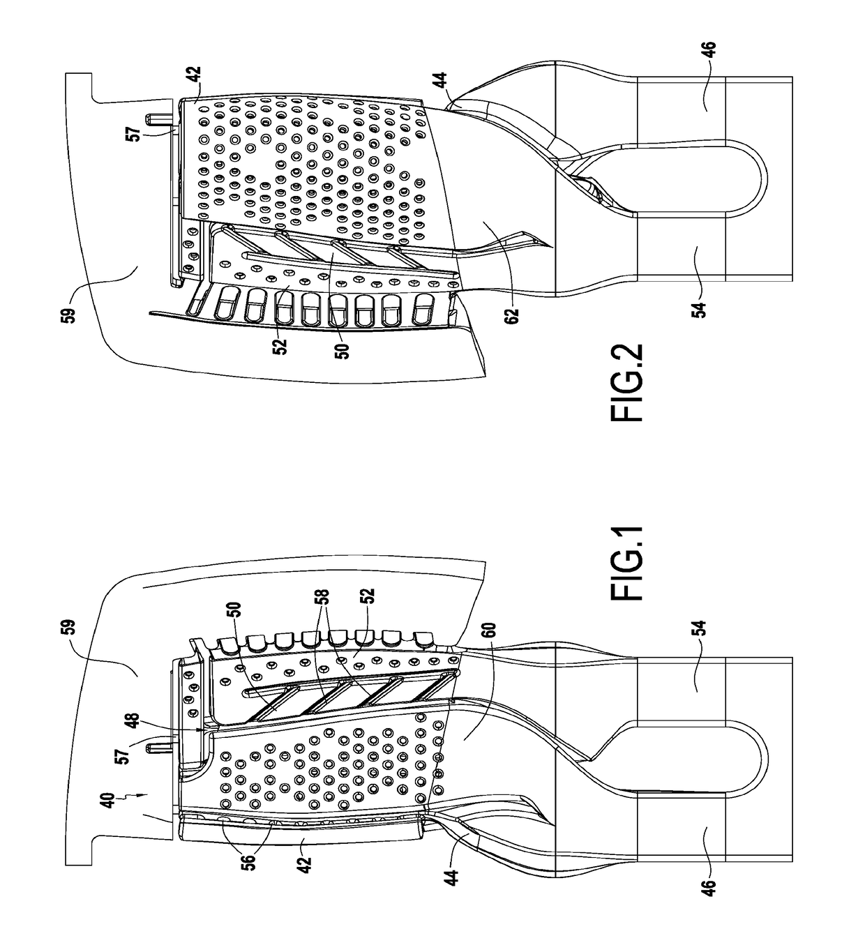
[0022]FIGS. 1 and 2 show a ceramic core 40 for making a turbine blade for a turbine engine, respectively in a suction side view and in a pressure side view relative to the blade. The ceramic core, in the example shown, comprises seven portions or columns forming a single element. The first column 42, which is to be located on the side where the combustion gas arrives, corresponds to the leading edge cavity 28 that is to be created after casting, whereas the second column 44 corresponds to the central cavity 20, which is adjacent thereto. This cavity receives a stream of cooling air via a channel (not shown) that results, after casting, from the presence of a first column root 46 of the core 40. The other three columns 48, 50, and 52 follow go-and-return paths and correspond to the following cavities 22, 30, and 32, which receive a second cooling air stream conveyed by another channel resulting from the presence of a second column root 54 connected to the first column root 46 in orde...


PUM

PropertyMeasurementUnit
Mechanical strengthaaaaaaaaaa
Thicknessaaaaaaaaaa
Thermomechanical propertiesaaaaaaaaaa

Abstract

A ceramic core used for fabricating a hollow turbine blade for a turbine engine by using the lost-wax casting technique and shaped to constitute the cavities of the blade as a single element, includes, in order to feed the insides of these cavities jointly with cooling air, core portions that are to form first and second lateral cavities and that are connected to a core portion that is to form at least one central cavity, firstly in the core root via at least two ceramic junctions, and secondly at various heights up the core via a plurality of other ceramic junctions of positioning that defines the thickness of the internal partitions of the blade, while also ensuring additional cooling air for predetermined critical zones of the first and second lateral cavities.

Description

FIELD OF THE INVENTION[0001]The present invention relates to the general field of sets of blades for a turbine engine turbine, and more particularly to turbine blades having cooling circuits incorporated therein and made by the lost-wax casting technique.PRIOR ART[0002]In known manner, a turbine engine includes a combustion chamber in which air and fuel are mixed together prior to being burnt therein. The gas resulting from such combustion flows downstream from the combustion chamber and then feeds a high-pressure turbine and a low-pressure turbine. Each turbine comprises one or more stationary vane rows (known as nozzles) alternating with one or more moving blade rows (referred to as rotor wheels), in which rows the blades or vanes are spaced apart circumferentially all around the rotor of the turbine. Such turbine blades or vanes are subjected to the very high temperatures of the combustion gas, which temperatures reach values that are well above those that can be withstood withou...

Claims


Application Information

Patent Timeline
IPC IPC(8): F01D5/28F01D5/18
CPCF01D5/284F01D5/18F05D2240/305F05D2230/21F05D2300/20F01D5/187F05D2230/211B22C9/04B22C9/10
Inventor PAQUIN, SYLVAINDUJOL, CHARLOTTE MARIEENEAU, PATRICEJOUBERT, HUGUES DENISROLLINGER, ADRIEN BERNARD VINCENT
Owner SN DETUDE & DE CONSTR DE MOTEURS DAVIATION S N E C M A
Why Eureka
Try Eureka