Heart valve prosthesis delivery system and method for delivery of heart valve prosthesis with introducer sheath

Pending Publication Date: 2018-05-03
JENAVALVE TECH
View PDF0 Cites 54 Cited by
  • Summary
  • Abstract
  • Description
  • Claims
  • Application Information

AI Technical Summary

Benefits of technology

[0089]at least one and preferably three positioning hoops, which are designed to engage in pockets of the native heart valve in the implanted state of the stent, thus to enable automatic positioning of the stent in the aorta of the patient.
[0090]In particular, a catheter system is disclosed herein, with which an expandable heart valve stent with a heart valve prosthesis attached to this stent can be advanced to the implantation site in a particularly simple way, for e

Problems solved by technology

The requirements for the catheter by way of transfemoral delivery is more complex as compared with the transapical route because for the delivery of e.g. an aortic heart valve a relatively long distance and bends have to be manoevered through which imply certain difficulties.
Accordingly the prosthesis has to be squeezed together which implies the risk of damaging the pericard material of the valve.
Moreover, the correct positioning is another issue and possibly the capability of the catheter system of repositioning the prosthesis during the course of delivering and applying the prosthesis at the target site and position in the patient.
Another issue is the diameter seize of catheter system.
Many known systems do not achieve an adequate crimping seize and often the tissue is negatively affected in known systems during the crimping procedure.
Moreover, the crimping of the prosthesis as such represents a challenge.
In particular crimping in a manner without damaging, or stretching and/or squeezing the tissue of the prosthesis is often not sufficiently achieved in known systems.
Even though immediate damages due to the crimping may not be obvious, often the tissue is still negatively affected by the crimping with a negative impact on the durability of the tissue, e.g. pericard tissue, represen

Method used


Image

  • Heart valve prosthesis delivery system and method for delivery of heart valve prosthesis with introducer sheath
  • Heart valve prosthesis delivery system and method for delivery of heart valve prosthesis with introducer sheath
  • Heart valve prosthesis delivery system and method for delivery of heart valve prosthesis with introducer sheath

Examples


Embodiment Construction

[0119]In the following, exemplary embodiments of the present disclosure will be described in more detail.

[0120]FIG. 5 shows schematically an example of how a transarterial or transfemoral access can be gained to the heart of a patient. In the illustration in accordance with FIG. 5, a heart valve stent 150 is advanced with the aid of a delivery system 100 via the femoral artery to the aortic valve. Embodiments of a delivery system 100, which is suitable for transarterial or transfemoral access, are described in the following.

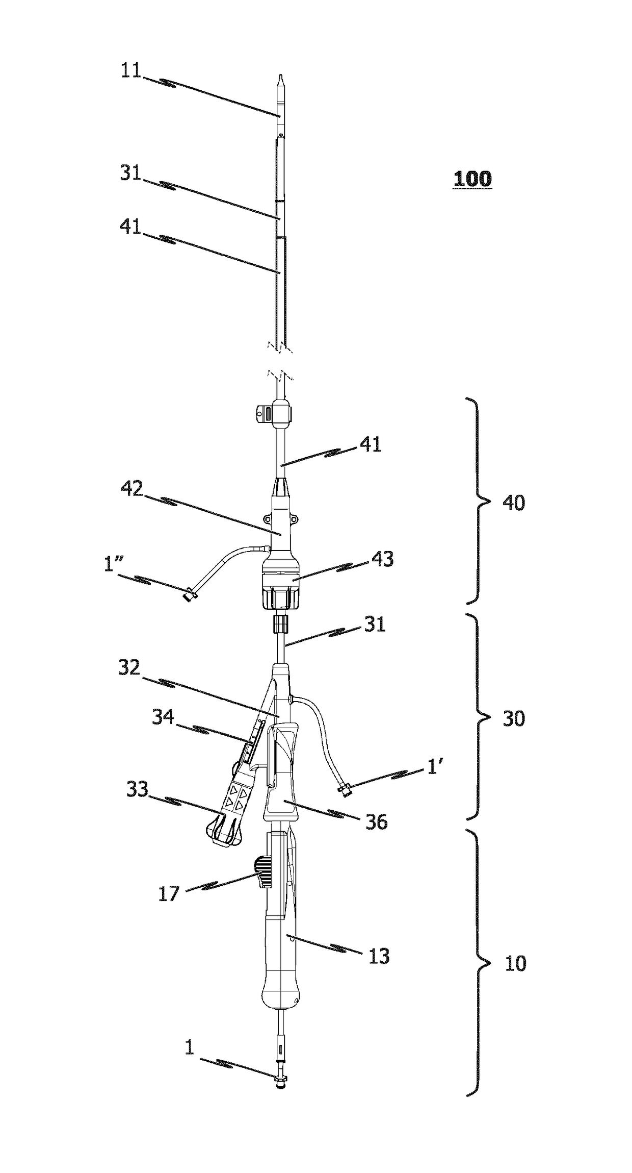
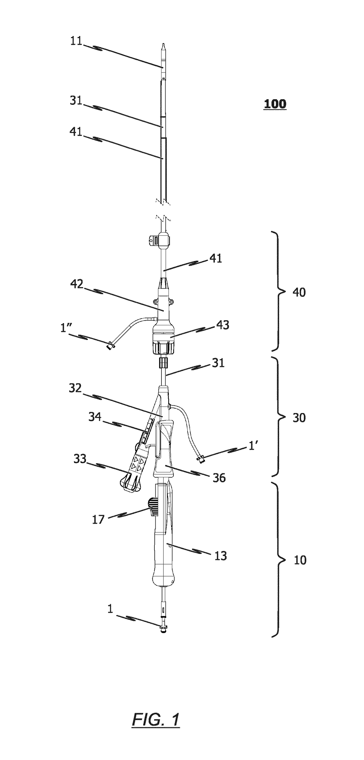
[0121]As depicted, for example, in FIG. 1, the delivery system 100 according to an exemplary embodiment of the present disclosure comprises delivery means 10, steering means 30, and an introducer 40.

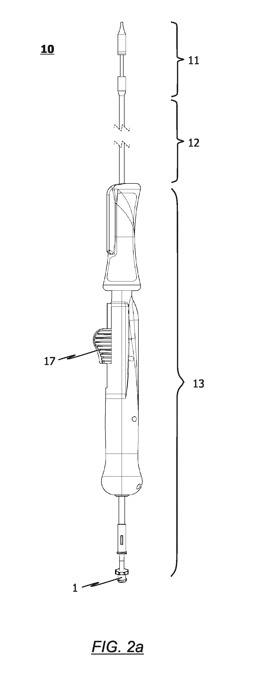
[0122]The delivery means 10 has a catheter tip 11, a catheter shaft 12, and a handle 13 connected to the proximal end section of the catheter shaft 12. In this regard, reference is also made to FIG. 2a and FIG. 2b.

[0123]As illustrated, for example, in FIG. 2c, the ca...


PUM


Abstract

The present disclosure relates to a delivery system, a catheter system and a method for the minimally invasive application of prostheses to an individual in need thereof and a method for loading a prosthesis onto a catheter system and/or a delivery system.

Description

[0001]The present disclosure relates to a delivery system, a catheter system and a method for the minimally invasive application of prostheses to an individual in need thereof and a method for loading a prosthesis onto a catheter system and / or a delivery system.[0002]This application is related case of EP13173217.4 & EP13182346.0, U.S. Pat. No. 8,790,395 and US patent publication 2014 / 0081388A1 (Mar. 20, 2014) all assigned to the instant assignee, the entire disclosures of which are incorporated herein by reference, each as if expressly set forth.BACKGROUND[0003]The current disclosure relates to the field of medical devices, in particular to prosthesis which are being transplanted into an individual in need thereof in order to re-establish proper body functions by way of minimally invasive methods and means applicable therefor.[0004]Examples of prostheses that are placed by way of minimally invasive methods are stents and heart valves like aortic and mitral heart valves. Heart valve...

Claims


Application Information

Patent Timeline
IPC IPC(8): A61F2/966A61F2/24A61F2/07A61F2/86
CPCA61F2/966A61F2/2433A61F2/2436A61F2/07A61F2/2418A61F2/86A61F2002/9505A61F2002/9517A61F2002/9522A61M25/0136A61M2025/0681A61F2002/9583A61F2/2427A61F2250/0006A61F2/9522A61F2/24A61F2/95A61F2/9517
Inventor SCHRECK, STEFANJIMENEZ, JR., TEODORO S.CHARLTON, EILEENGOULD, WILLIAM
Owner JENAVALVE TECH
Why Eureka
Try Eureka