

Printing plate precursor, planographic printing plate, blank plate for printing, and laminate thereof
- Summary
- Abstract
- Description
- Claims
- Application Information
AI Technical Summary
Benefits of technology
Problems solved by technology
Method used
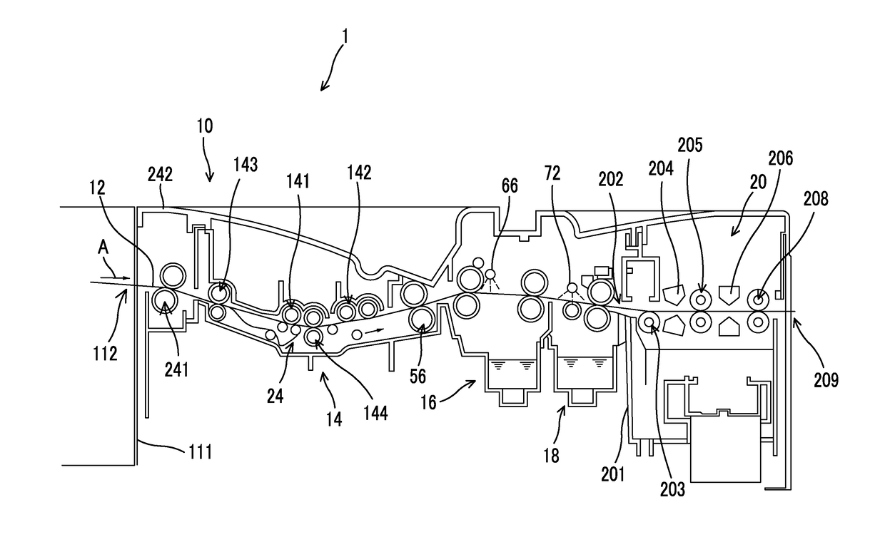
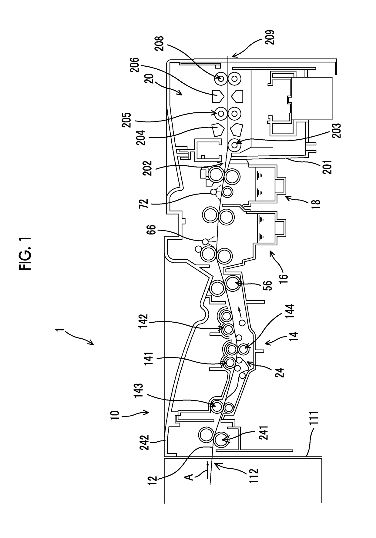
Image

Examples
examples
[0295]Hereinafter, the present invention will be described in detail with reference to examples, but the present invention is not limited thereto. Further, in a polymer compound, the molecular weight indicates the weight-average molecular mass (Mw) and the proportion of repeating units indicates mole percentage unless otherwise specified. Further, the mass average molecular weight (Mw) is a value in terms of polystyrene obtained by performing measurement using gel permeation chromatography (GPC).
examples 301 and 302
[0451][Preparation of Planographic Printing Plate Precursor 301]
[0452]
[0453]The other surface (the surface which did not have the back coat layer) of the support having the back coat layer used for the preparation of the planographic printing plate precursor 101 was coated with an undercoat layer coating solution (2) having the following composition using a wire bar and dried at 90° C. for 30 seconds. The coating amount thereof was 10 mg / m2.
[0454](Undercoat Layer Coating Solution (2))
Polymer compound A (the following structure) (mass average molecular weight:0.05 g3000)Methanol27 gIon exchange water3 g
[0455]
[0456]The undercoat layer was coated with the image recording layer coating solution (3) having the following composition using a wire bar and dried at 115° C. for 34 seconds using a hot air dryer. The coating amount after the drying was 1.4 g / m2.
[0457](Image Recording Layer Coating Solution (3))
Infrared absorbent (IR-1) (the following structure)0.074 gPolymerization initiator (O...
examples 401 and 402
[0484][Preparation of Blank Plate Precursor 401 for Printing]
[0485]A blank plate precursor 401 for printing was prepared in the same manner as that for the planographic printing plate precursor 101 except that an infrared absorbent (1) was removed from the image recording layer coating solution (1).
[0486][Preparation of Blank Plate Precursor 402 for Printing]
[0487]
[0488]The other surface (the surface which did not have the back coat layer) of the support having the back coat layer used for the preparation of the planographic printing plate precursor 101 was bar-coated with an undercoat layer coating solution (4) having the following composition and dried at 100° C. for 20 seconds, thereby forming an undercoat layer. The coating amount after the drying was 20 mg / m2.
[0489]
Polymer (the following structure)0.3 parts by massPure water60.0 parts by massMethanol939.7 parts by mass
[0490]
[0491]The undercoat layer was bar-coated with a non-photosensitive layer coating solution (1) having the ...
PUM
| Property | Measurement | Unit |
|---|---|---|
| Length | aaaaa | aaaaa |
| Particle diameter | aaaaa | aaaaa |
| Temperature | aaaaa | aaaaa |
Abstract
Description
Claims
Application Information