Optical shape sensing system and method for sensing a position and/or shape of a medical device using backscatter reflectometry

a technology of optical shape and position, applied in the field of optical shape sensing system and method for sensing the position and/or shape of a medical device using backscatter reflectometry, can solve the problems of insufficient scanning/sweeping speed of the laser, prone to vibration, and insufficiently fulfilling the requirement of the art, so as to avoid the data scrambling of adjacent fiber position more easily

Active Publication Date: 2018-05-10
KONINKLJIJKE PHILIPS NV
View PDF9 Cites 9 Cited by
  • Summary
  • Abstract
  • Description
  • Claims
  • Application Information

AI Technical Summary

Benefits of technology

[0008]It is an object of the present invention to provide an optical shape sensing system and method for sensing a position and/or shape of a medical device which enable optical shape sensing based on backscatter reflectom...

Problems solved by technology

However, the TLS known in the art do not sufficiently fulfill this requirement.
Thirdly, the scanning/sweeping speed of the laser should be sufficiently large.
These devices are ma...

Method used


Image

  • Optical shape sensing system and method for sensing a position and/or shape of a medical device using backscatter reflectometry
  • Optical shape sensing system and method for sensing a position and/or shape of a medical device using backscatter reflectometry
  • Optical shape sensing system and method for sensing a position and/or shape of a medical device using backscatter reflectometry

Examples


Embodiment Construction

[0042]Optical shape sensing (OSS) may be performed using three techniques: first, strain sensing using spectroscopy; second, distributed sensing using interferometry; and third, shape reconstruction using a special fiber geometry. State of the art techniques in OSS are based on strain sensing which entails the measurement of spectral shifts. Here, the typical measurement sensitivity is about 1.2 pm / με, wherein one με corresponds to a relative length increase of 10−6. In this way, the typical measurement sensitivity is determined by the minimal detectable wavelength shift.

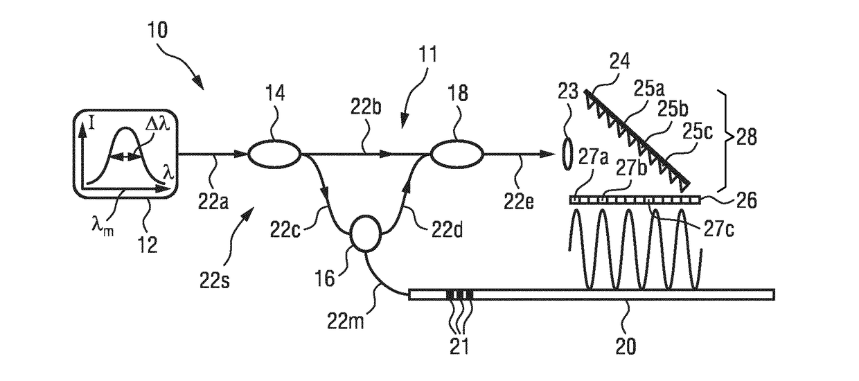
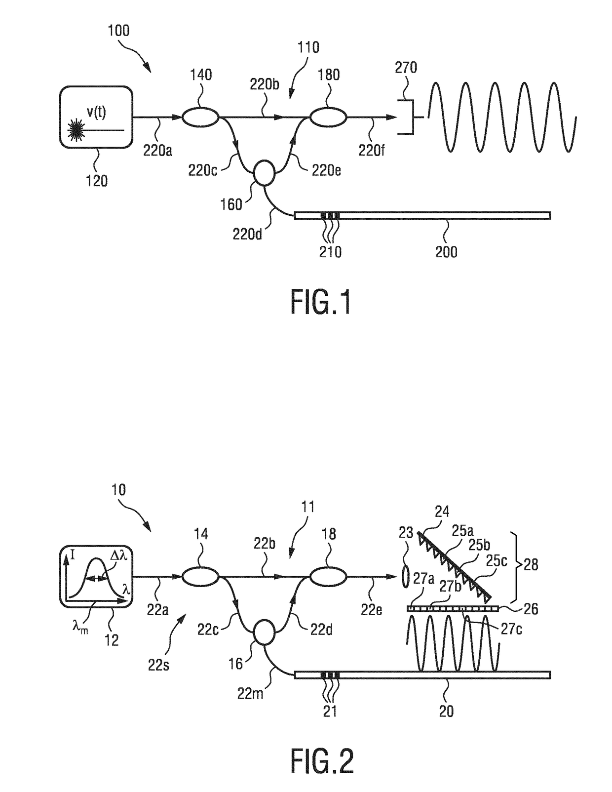
[0043]Interferometry enables distributed sensing with a high spatial resolution. For instance, methods known in the past use a swept laser source or tunable laser source (TLS) so that the various strain sensors measured based on Bragg gratings can be distinguished from one another even when their spectral response is the same.

[0044]Each position within the fiber sensor is characterized by its own beat frequency whic...


PUM


Abstract

Optical shape sensing system for sensing a position and/or shape of a medical device (20) using backscatter reflectometry, comprising a broadband light source (12) for generating input light of multiple wavelengths of a broadband spectrum, an interferometer arrangement (11) comprising a plurality of interferometers including a multi-core optical fiber (22m, 30), the multi-core optical fiber (22m, 30) comprising at least two fiber cores (31, 32a,b,c), wherein each of the interferometers is configured to perform backscatter reflectometry separately with a corresponding one of a plurality of input light beams divided from the input light and comprises a fiber splitter (14) for dividing the corresponding input light beam into a reference beam and a device beam, an additional optical fiber (22s) for guiding the reference beam, a corresponding fiber core (31, 32a,b,c) of the multi-core optical fiber (22m, 30) for guiding the device beam to be reflected within the medical device (20) and for guiding the reflected device beam, and a fiber coupler (18) for coupling the reflected device beam with the reference beam to form an output light beam, the optical shape sensing system further comprising a spectrometer (28) for receiving and interacting with the output light beam, the spectrometer (28) comprising a detector unit (26) for detecting the output light beam.

Description

FIELD OF THE INVENTION[0001]The present invention relates to an optical shape sensing system and method for sensing a position and / or shape of a medical device using backscatter reflectometry. It finds application in minimal invasive intervention techniques, in particular in elongated medical devices such as fibers, endoscopes, catheters or guidewires.BACKGROUND OF THE INVENTION[0002]Optical shape sensing (OSS) is an optical measurement technique for determining the position and shape of a structure in a three-dimensional space. The Optical Shape Sensing (OSS) technology is also called Fiber-optical RealShape (FORS) technology. Optical Shape Sensing can be applied in minimal invasive procedures in healthcare, wherein it is advantageous to monitor the three-dimensional shape of an elongated medical device within the body of a patient.[0003]To this end, the OSS is based on three techniques: first, strain sensing using spectroscopy; second, distributed sensing using interferometry; and...

Claims


Application Information

Patent Timeline
IPC IPC(8): G01B11/16A61B1/00A61B5/06A61M25/01G01B11/24G01B9/02
CPCG01B11/161A61B1/00147A61B1/00163A61B5/065G01B11/18A61M25/01G01B11/2441G01B9/02004G01B9/02027A61B34/20A61B2034/2061
Inventor 'T HOOFT, GERT WIM
Owner KONINKLJIJKE PHILIPS NV
Why Eureka
Try Eureka