Eureka AIR delivers breakthrough ideas for toughest innovation challenges, trusted by R&D personnel around the world.

Parallel interconnection of neighboring space-qualified solar cells via a common back plane

a solar cell and parallel connection technology, applied in the field of photovoltaic power devices, can solve the problems of increasing the overall cost of the photovoltaic array or panel, inefficient use of the surface on which the solar cell is mounted, and inefficient use of the available space, so as to achieve high wafer utilization

Active Publication Date: 2018-05-17
SOLAERO TECH CORP
View PDF6 Cites 6 Cited by
  • Summary
  • Abstract
  • Description
  • Claims
  • Application Information

AI Technical Summary

Benefits of technology

The patent describes a method for easily assembling a large number of solar cells using a support with a continuous conductive layer. The solar cells can be small and easily placed on the support, and the connections between them can be made with a conductive bonding material. The use of a conductive bonding material helps to improve heat transfer and prevent cracking. The support can be made of copper or other metal alloy that matches the thermal expansion characteristics of the solar cells. The first contact of each solar cell has a conductive layer, which helps to establish a good connection with the support. Overall, this method allows for efficient use of space and improved performance of solar cell assemblies.

Problems solved by technology

Arrays of substantially circular solar cells are known to involve the drawback of inefficient use of the surface on which the solar cells are mounted, due to space that is not covered by the circular solar cells due to the space that is left between adjacent solar cells due to their circular configuration (cf.
However, as explained above, for assembly into a solar array (henceforth, also referred to as a solar cell assembly), substantially circular solar cells, which can be produced from substantially circular wafers to minimize waste of wafer material and, therefore, minimize solar cell cost, are often not the best option, due to their low array fill factor, which increases the overall cost of the photovoltaic array or panel and implies an inefficient use of available space.
However, when a single circular wafer is divided into a single rectangle, the wafer utilization is low.
This results in waste.
High efficiency solar cell wafers are often costly to produce.
Thus, the waste that has conventionally been accepted in the art as the price to pay for a high fill factor, that is, the waste that is the result of cutting the rectangular solar cell out of the substantially circular solar cell wafer, can imply a considerable cost.
This implies that less wafer material is wasted than in the case of the option shown in FIG. 1, but also a less efficient use of the surface on which the solar cells are mounted, due to the lower fill factor.
A further problem is that with this kind of layout, the pattern features a hexagonal unit cell 2000 (illustrated with broken lines in FIG. 2), which is non-optimal for producing a rectangular assembly of solar cells.
The hexagonal unit cell is inconvenient for producing rectangular arrays of solar cells because the assembly of solar cells will not fit neatly to the edges or boundaries of a rectangular panel.
However, whereas this approach makes it possible to reduce the waste of wafer material, it is non-optimal from the point of view of the fill factor, as when the rectangular solar cells with cropped corners are placed in rows and columns to form a solar cell array, the space where the cropped corners meet is left without solar cell material and is thus not used for the conversion of light into electric power.
However, the use of a large number of relatively small solar cell involves the drawback that for a given effective surface area of the final solar cell assembly, there is an increased number of interconnections between solar cells, in parallel and / or in series, which may render the process of manufacturing the solar cell assembly more complex and / or expensive, and which may also render the entire circuit less reliable, due to the risk for errors due to defective interconnections between individual solar cells.

Method used


Image

  • Parallel interconnection of neighboring space-qualified solar cells via a common back plane
  • Parallel interconnection of neighboring space-qualified solar cells via a common back plane
  • Parallel interconnection of neighboring space-qualified solar cells via a common back plane

Examples


Embodiment Construction

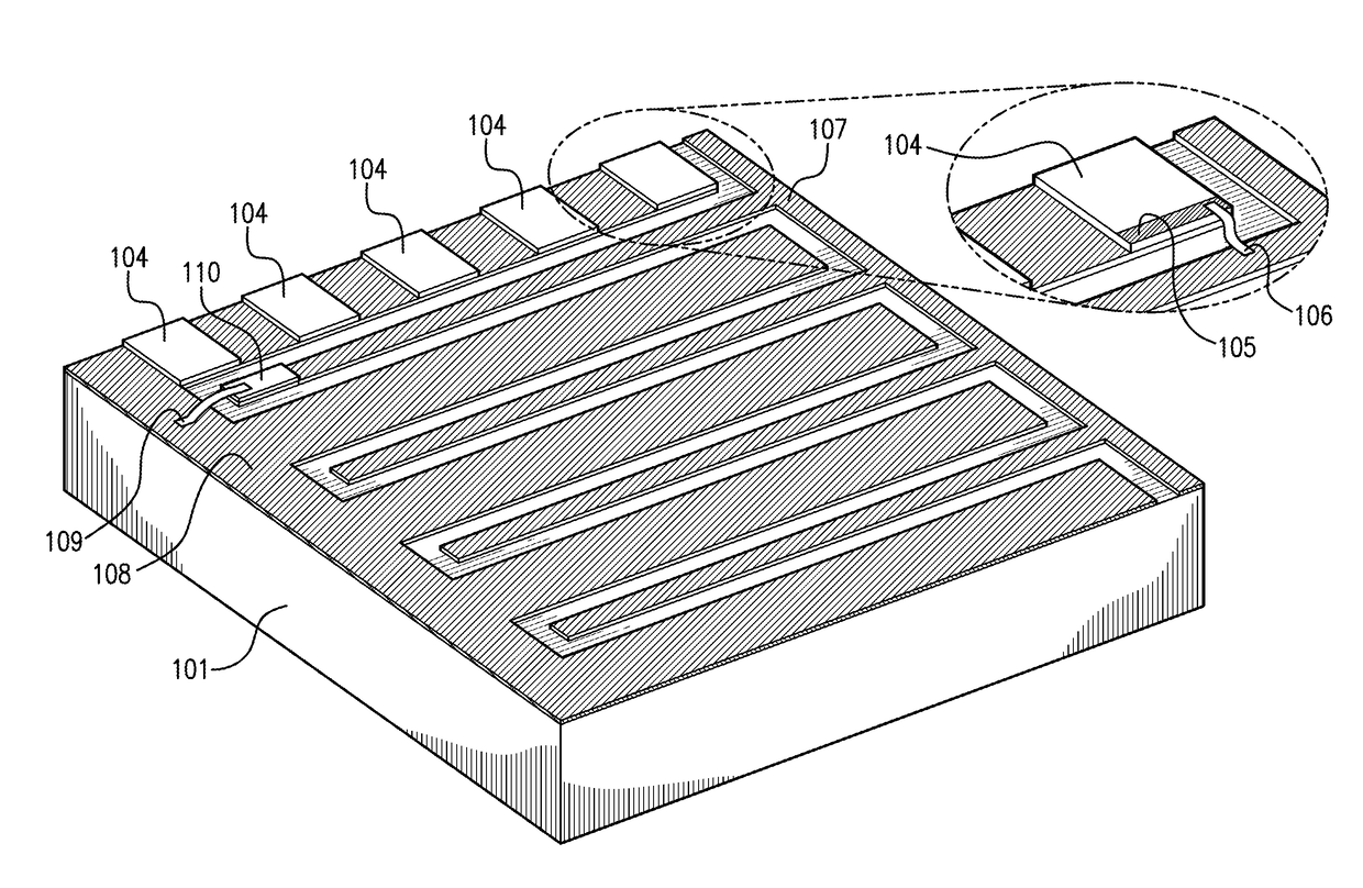
[0038]The present disclosure provides a process for the design and fabrication of a solar cell array panel for space application utilizing interconnected modular subassemblies. Although principally concerned with the structure and organization of the modular subassemblies, the solar cells are essential components of such subassemblies, and thus a discussion of III-V compound semiconductor solar cells is in order here.

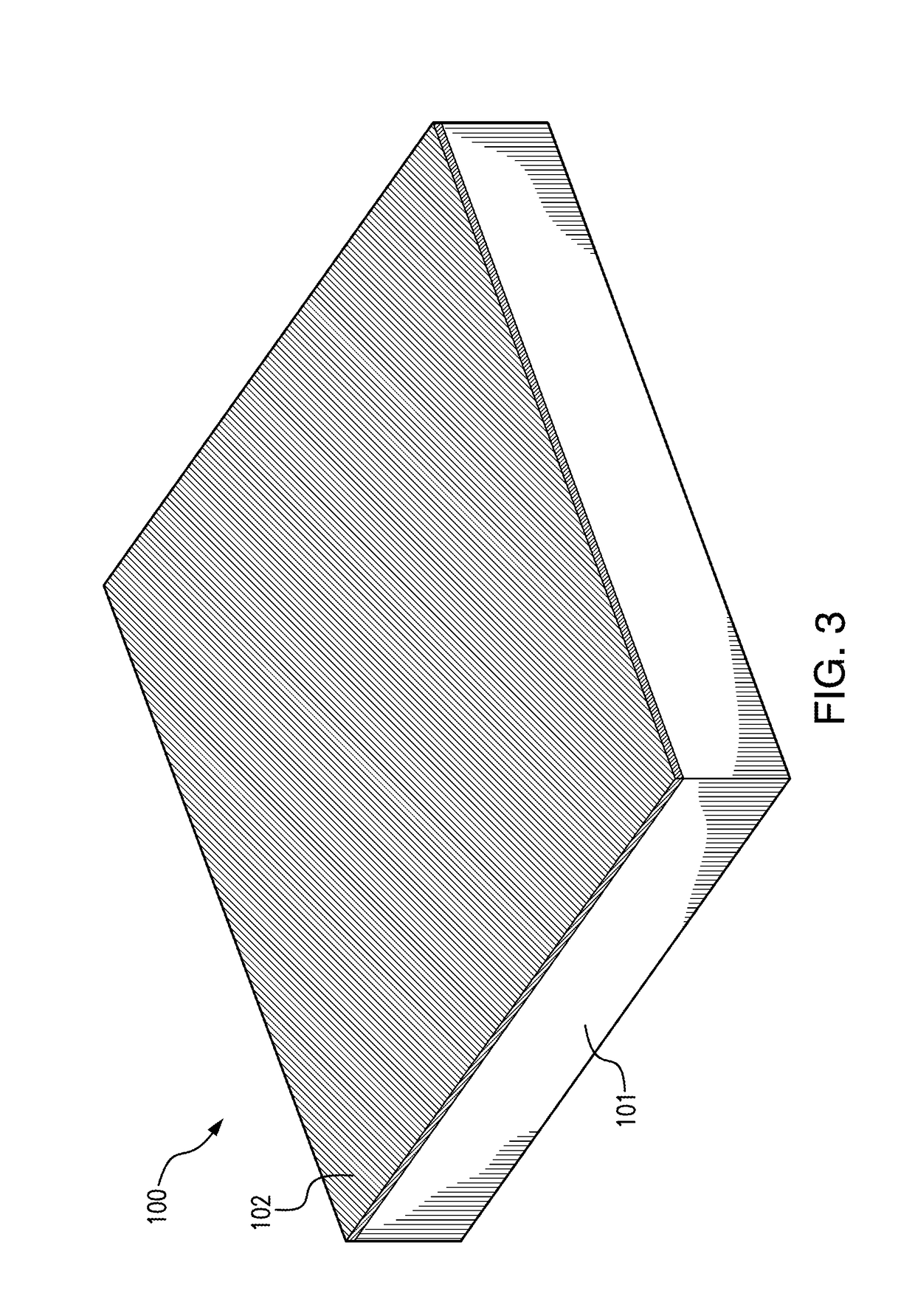
[0039]FIG. 3 illustrates an example of a support that can be used in an embodiment of the disclosure. The support comprises an insulating support layer 101 and a conductive metal layer 102 arranged on a top surface of the support layer 101. In some embodiments of the disclosure, the metal layer 102 is a copper layer, having a thickness in the range of from 1 μm and up to 50 μm. In some embodiments of the disclosure, the support layer 101 is a Kapton® layer, that is, a polyimide film layer. Preferably the metal layer is attached to the support layer in an adhesive-less m...


PUM


Abstract

A solar cell assembly for space application comprising a plurality of space-qualified solar cells and a support, the support comprising a conductive layer. The conductive layer is divided into a first conductive portion and a second conductive portion. Each space-qualified solar cell of the plurality of space-qualified solar cells comprising a front surface, a rear surface, and a first contact in correspondence with the rear surface. Each one of the plurality of space-qualified solar cells is placed on the first conductive portion with the first contact electrically connected to the first conductive portion so that the space-qualified solar cells are connected in parallel through the first conductive portion. A second contact of each space-qualified solar cell can be connected to the second conductive portion. The two conductive portions serve as bus bars of the space-qualified solar cell assembly.

Description

REFERENCE TO RELATED APPLICATIONS[0001]The present application is a continuation-in-part of U.S. patent application Ser. No. 14 / 592,519, file Jan. 8, 2015, which claims the benefit of U.S. Provisional Application No. 61 / 976,108 filed Apr. 7, 2014, which are incorporated herein by reference in their entirety.BACKGROUND OF THE DISCLOSURE1. Field of the Disclosure[0002]The disclosure relates to the field of photovoltaic power devices.2. Description of the Related Art[0003]Satellite and other space related applications typically use solar cells designed for use in the space environment, i.e., under the AM0 solar spectrum. Such space-qualified solar cells have a sequence of subcells with compositions and band gaps that have been optimized to achieve maximum efficiency for the AM0 spectrum, which is different from the compositions and band gaps of terrestrial solar cells, which are optimized for the AM1.5 solar spectrum.[0004]Another distinctive difference between space-qualified solar ce...

Claims


Application Information

Patent Timeline
Patent Type & Authority Applications(United States)
IPC IPC(8): H01L31/18H01L31/0725H01L31/05H01L31/048H01L31/02
CPCH01L31/184H01L31/0725H01L31/0512H01L31/0481H01L31/0508H01L31/02008Y02E10/544Y02P70/50Y02E10/50H01L31/02002H01L31/02016
Inventor AIKEN, DANIELDERKACS, DANIEL
Owner SOLAERO TECH CORP
Why Eureka
Eureka Blog
Learn More