Catalyst support and related processes

Active Publication Date: 2018-06-07
BRASKEM SA
View PDF4 Cites 0 Cited by
  • Summary
  • Abstract
  • Description
  • Claims
  • Application Information

AI Technical Summary

Benefits of technology

[0014](iv) The precipitation of solid particles occurs through the passage of said alcoholic solutions into an atomizer located inside a reactor under inert atmosphere and pressure between 1 and 2 bar. The reactor contains a non-solvent hydrocarbon at low temperature. The solution is sprayed into small droplets, which is

Problems solved by technology

For example, rapid removal of alcohol can lead to formation of fragile hollow particles, which are not suitable for the production of ZN catalysts due to the poor mechanical strength of the particles.
It describes the application of a solution of MgCl2 with alcohol, which is heated from 40 to 100° C. This solution is then dispersed through a spray nozzle

Method used


Image

  • Catalyst support and related processes
  • Catalyst support and related processes
  • Catalyst support and related processes

Examples


Example

Example 1

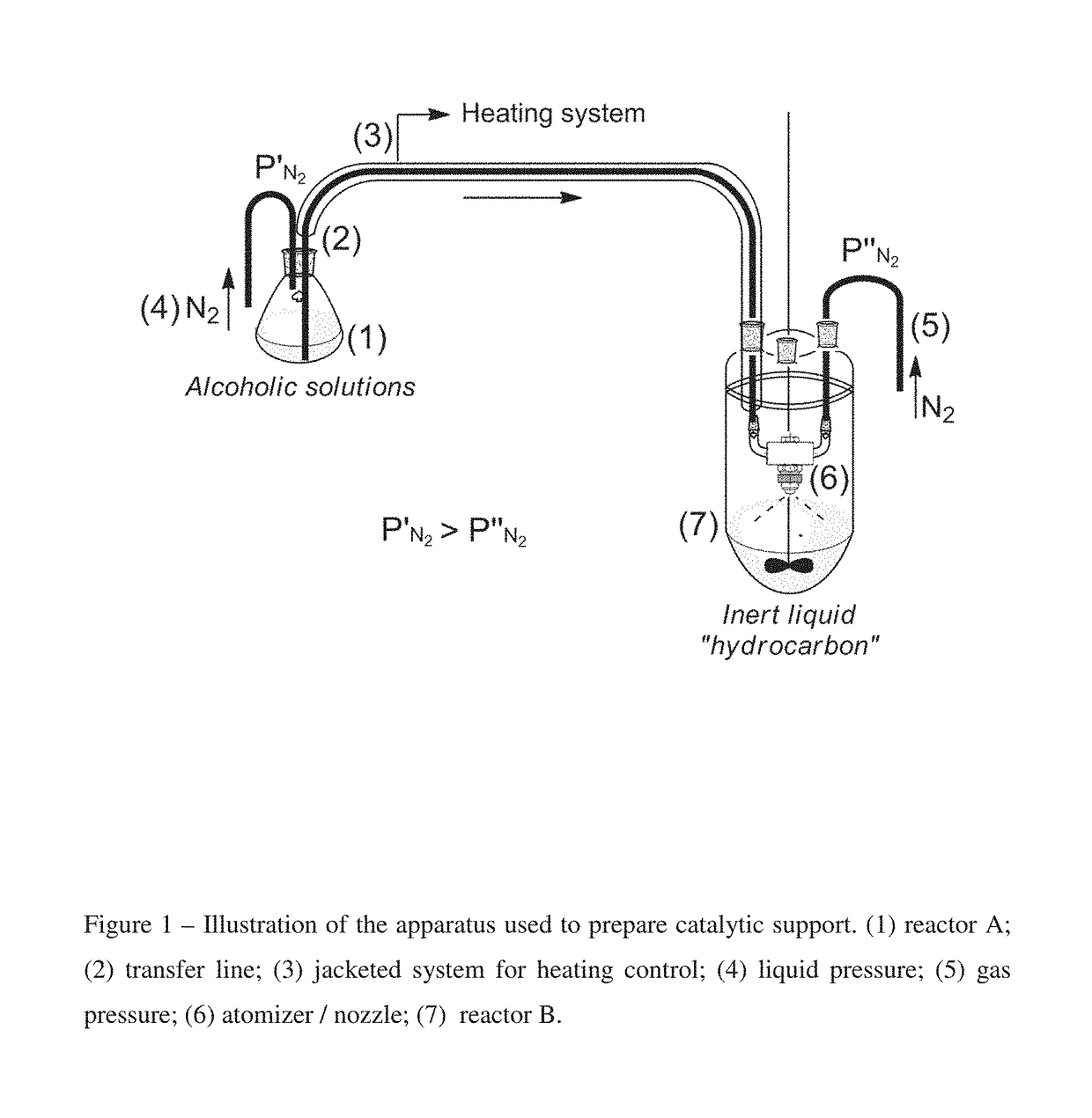
[0053]A solution of MgCl2 anhydride in ethanol at 4.0 wt % was prepared at room temperature. This solution was transferred through ⅛″OD jacketed tubing with controlled temperature connected to an atomizer (gas atomizer nozzle) placed inside a 5 L rounded-bottom flask to spray droplets of the alcoholic solution to dried isoparaffin at low temperature, approximately −20° C. The pressure applied in reactor A (1) and system (4) to transfer initial alcoholic solution to the atomizer was 0.7 bar, while the N2 pressure (5) was 1.0 bar. The resulting suspension of the particles precipitated in isoparaffin was stirred overnight at 350 RPM. After stirring, the mixture was left for 3 hours and then the supernatant was removed and 1 L of dried hexane was added to form a suspension with the resulting particles. The resulting mixture was transferred through cannula to a Schlenk flask followed by the filtration and recovering of the particles, which was washed several times with anhydride...

Example

Example 2

[0054]A solution of MgCl2 anhydride in ethanol at 12.2 wt % was prepared at 60° C. This solution was transferred through ⅛″OD jacketed tubing with controlled temperature directly to a 5 L rounded-bottom flask without the use of the atomizer. The alcoholic solution was transferred to dried isoparaffin at low temperature, at approximately −20° C. The resulting suspension of the particles precipitated in isoparaffin was stirred overnight at 350 RPM. After stirring, the mixture was left for 3 hours and then the supernatant was removed and 1 L of dried hexane was added to form a suspension with the resulting particles. The resulting mixture was transferred through cannula to a Schlenk flask followed by the filtration and recovering of the particles, which was washed several times with anhydride hexane and dried under nitrogen flow. All steps of this experiment were carried out under N2 atmosphere to obtain support sample SSB02.

Example

Example 3

[0055]The support catalyst was prepared as described in Example 2, followed by an additional step to remove the excess of ethanol from the obtained particles through a thermal treatment, as follows: the support was transferred to a Schlenk filter and kept under countercurrent nitrogen flow inside an oven for 1 hour at each temperature 40° C., 50° C. and, 60° C. to obtain support SSB03.


PUM

PropertyMeasurementUnit
Temperatureaaaaaaaaaa

Abstract

The present invention describes a catalyst support, which is used as an inorganic carrier for a Ziegler-Nata catalyst (ZN), using a modified spray cooling method. Such a catalyst support is prepared from alcoholic solutions of (a) an inorganic compound, in which the inorganic compound is a magnesium compound and (b) an inorganic compound and one or more additives. The solutions are prepared at a temperature below 100° C., carried through a nozzle placed inside a reactor, and sprayed into droplets forming a solid precipitate, which is generally spherical, when in contact with an inert hydrocarbon solvent at low temperature. The obtained catalyst support is reacted with a titanium compound, preferably titanium tetrachloride, in order to produce an active catalyst for olefin polymerization.

Description

CROSS-REFERENCE TO RELATED APPLICATIONS[0001]This application is a continuation-in-part of U.S. Ser. No. 15 / 105,788, filed Jun. 17, 2016.BACKGROUND OF THE INVENTION[0002]Catalytic supports based on magnesium compounds, particularly magnesium chloride (MgCl2), are the most effective for the production of Ziegler-Natta (ZN) catalysts for olefin polymerization. Perhaps one of the main advantages to use an inorganic carrier for a ZN catalyst is the control of the morphology, which enables the production of polymer with predictable shape, bulk density and particle size distribution due to the replica phenomenon. Given the importance of the support nature and its crystallization, it is important to explore alternatives routes for support preparation.[0003]Since the early 1970s, the patent literature and scientific articles have described routes to prepare spherical support from magnesium halides. One of the most important and widely used routes to obtain spherical and porous particles is ...

Claims


Application Information

Patent Timeline
IPC IPC(8): C08F4/02B01J35/00B01J35/08B01J37/00B01J37/06C08L23/02C08L67/04C07C19/08C07C21/18C07C31/20
CPCC08F4/02B01J35/0006B01J35/08B01J37/0072B01J37/06C08L23/02C08L67/04C07C19/08C07C21/18C07C31/202C08F2410/01C08L2314/02C08F110/06C08F2410/06C08F4/651C08F4/6545C08F4/6465C08F4/022C08F2500/04C08F2500/12C08F2500/15C08F2500/24C08F2500/35
Inventor CARDOSO, RENATA DA SILVAFERNANDES, JONAS ALVESWASHBURGER, MARCIA REGINABARBOSA, CESAR AUGUSTO SALES
Owner BRASKEM SA
Why Eureka
Try Eureka