Wireless power receiver, wireless power transmission system using the same, and rectifier
- Summary
- Abstract
- Description
- Claims
- Application Information
AI Technical Summary
Benefits of technology
Problems solved by technology
Method used
Image

Examples
first embodiment
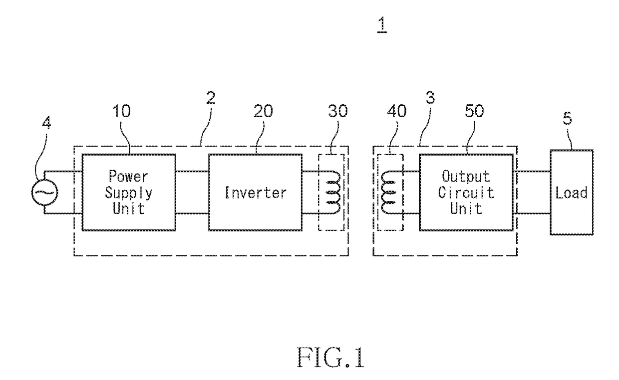
[0026]FIG. 1 is a block diagram showing a configuration of a wireless power transmission system according to the present invention.
[0027]As shown in FIG. 1, a wireless power transmission system 1 is configured by a combination of a power transmitting device 2 (wireless power transmitting device) and a power receiving device 3 (wireless power receiving device), and wirelessly transfers power from the power transmitting device 2 to the power receiving device 3.
[0028]The power transmitting device 2 includes a power supply unit 10 that converts an AC voltage supplied from an AC power supply 4 to a predetermined DC voltage, an inverter 20 that converts the DC voltage output from the power supply unit 10 to an AC voltage (rectangular wave) having a predetermined frequency (for example, 100 kHz), and a power feeding coil 30 that receives the AC voltage to generate a magnetic flux. The configuration of the power supply unit 10 is not particularly limited, and for example, the power supply u...
second embodiment
[0070]FIG. 12 is a circuit diagram showing a configuration of a power receiving device according to the
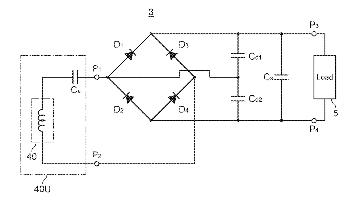
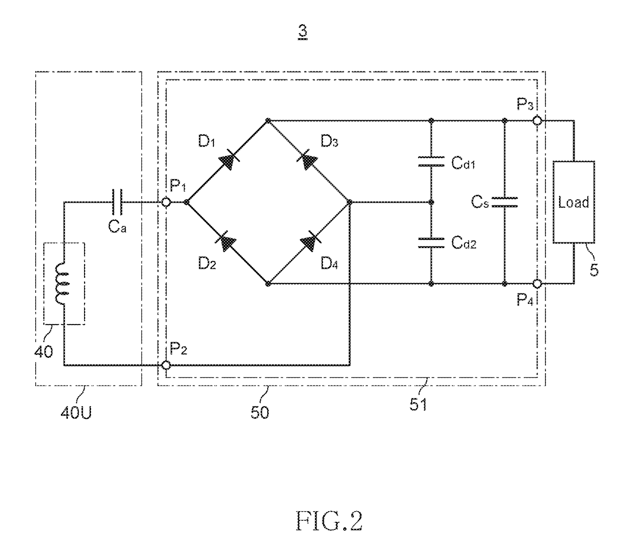
[0071]As shown in FIG. 12, the power receiving device 3 is characterized in that the first capacitor Cd1 is connected in parallel with the diode D1, and the second capacitor Cd2 is connected in parallel with the diode D2. Thus, the first capacitor Cd1 needs only to be connected in parallel with a diode, whose anode is connected to one input terminal P1 of the rectifier 51, of the plurality of diodes D1 to D4 configuring a bridge circuit, and the second capacitor Cd2 needs only to be connected in parallel with a diode, whose cathode is connected to the one input terminal P1 of the rectifier 51. Even with this configuration, identical effects as those of the first embodiment can be attained.
third embodiment
[0072]FIG. 13 is a circuit diagram showing a configuration of a power receiving device according to the
[0073]As shown in FIG. 13, the power receiving device 3 is characterized in that not only a series capacitor Ca is serially inserted, but also a series coil La and a parallel capacitor Cb are further inserted between the power receiving coil 40 and the bridge rectifier circuit. Thus, the configuration of an LC resonance circuit including the power receiving coil 40 is not particularly limited, and various circuit configurations can be adopted.
[0074]As described above, the wireless power transmission system 1 according to the first to third embodiments include the power transmitting device 2 that wirelessly supplies power, and the power receiving device 3 that receives power wirelessly supplied from the power transmitting device 2. The power receiving device 3 includes the power receiving coil 40 that takes in AC power via a magnetic field, and the rectifier 51 that converts the AC ...
PUM
 Abstract
Description
Claims
Application Information
 - Generate Ideas
- Intellectual Property
- Life Sciences
- Materials
- Tech Scout
- Unparalleled Data Quality
- Higher Quality Content
- 60% Fewer Hallucinations
Browse by: Latest US Patents, China's latest patents, Technical Efficacy Thesaurus, Application Domain, Technology Topic, Popular Technical Reports.
© 2025 PatSnap. All rights reserved.Legal|Privacy policy|Modern Slavery Act Transparency Statement|Sitemap|About US| Contact US: help@patsnap.com