Electroacoustic transduction film and manufacturing method thereof, electroacoustic transducer, flexible display, vocal cord microphone, sensor for musical instrument

Active Publication Date: 2018-06-07
FUJIFILM CORP
View PDF0 Cites 27 Cited by
  • Summary
  • Abstract
  • Description
  • Claims
  • Application Information

AI Technical Summary

Benefits of technology

[0029]According to the present invention, it is possible to provide the capable of reproducing a sound with a sufficient sound volume at a high conversion effici

Problems solved by technology

However, there is a limit to the control to increase the poling electric field during electric polarization processing, and the intensity ratio: (002) plane peak intensity/((002) plane peak intensity+(200) plan

Method used


Image

  • Electroacoustic transduction film and manufacturing method thereof, electroacoustic transducer, flexible display, vocal cord microphone, sensor for musical instrument
  • Electroacoustic transduction film and manufacturing method thereof, electroacoustic transducer, flexible display, vocal cord microphone, sensor for musical instrument
  • Electroacoustic transduction film and manufacturing method thereof, electroacoustic transducer, flexible display, vocal cord microphone, sensor for musical instrument

Examples


example 1

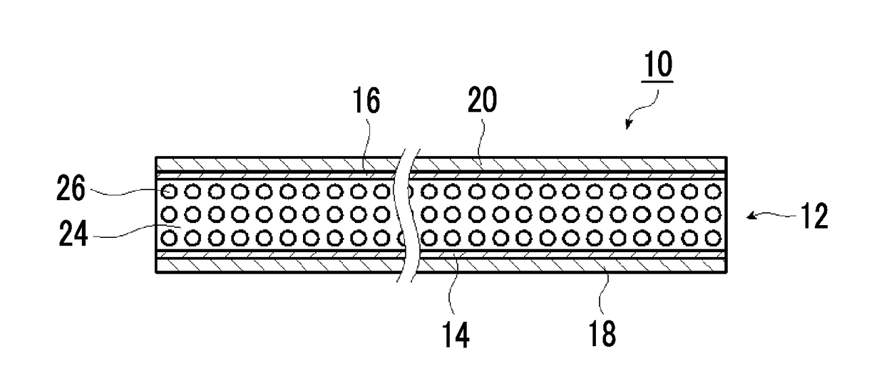
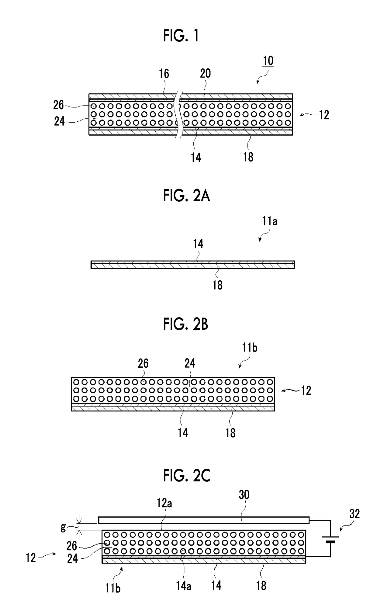
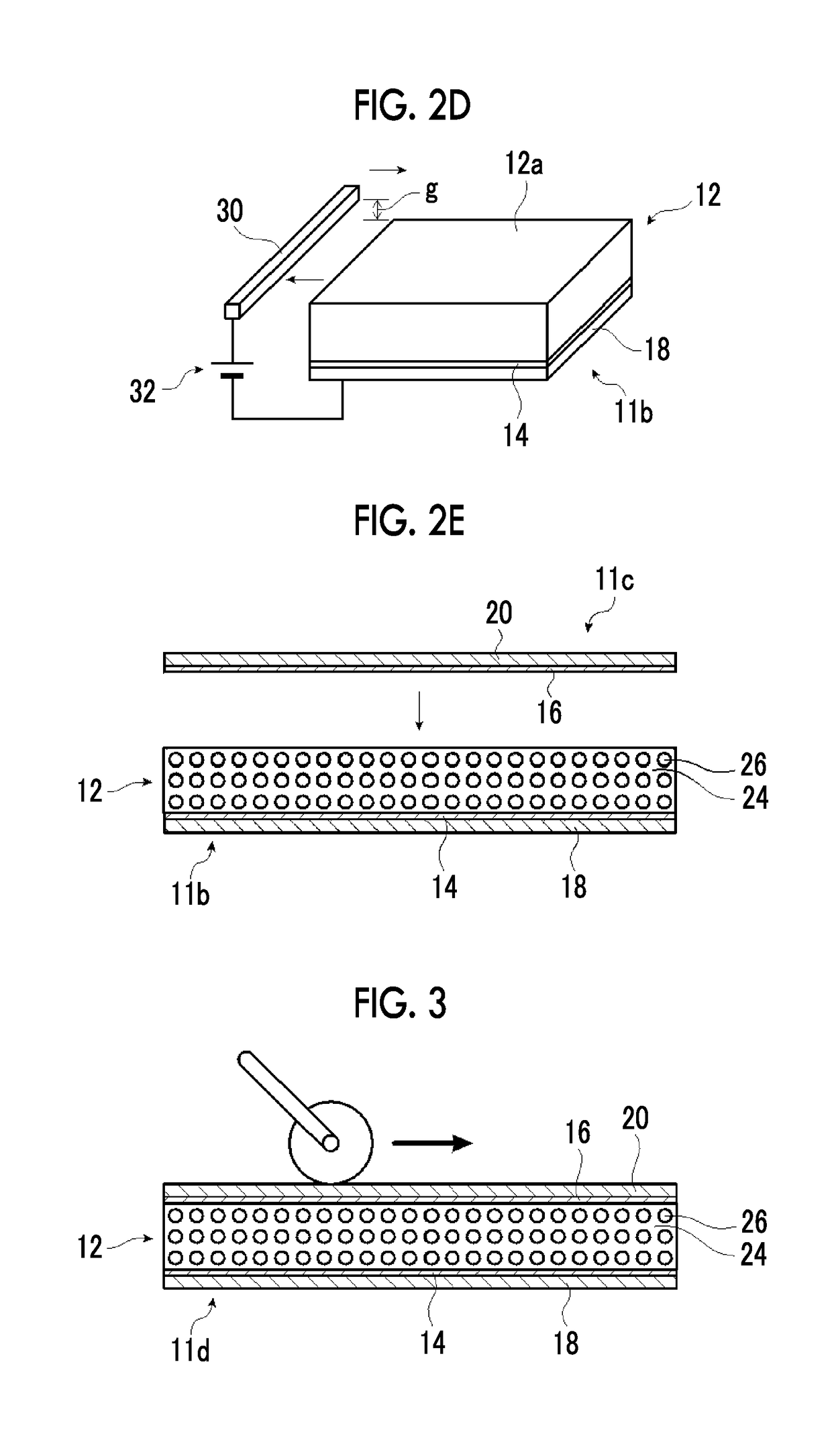
[0308]According to the method illustrated in FIGS. 2A to 2E and FIG. 3 described above, the transduction film 10 illustrated in FIG. 1 was prepared.

[0309](Preparation Step)

[0310]A lower electrode laminated body 11a and an upper electrode laminated body 11c in each of which a copper thin film having a thickness of 0.1 μm was vacuum vapor deposited on a PET film having a thickness of 4 μm were prepared. That is, in this example, the upper electrode 16 and the lower electrode 14 are copper vapor deposition thin films having a thickness of 0.1 μm, and the upper protective layer 20 and the lower protective layer 18 are PET films having a thickness of 4 μm.

[0311]In order to obtain good handleability during the process, as the PET film, a film with a separator (temporary supporter PET) having a thickness of 50 μm attached thereto was used, and the separator of each protective layer was removed after the thermal compression bonding of the upper electrode laminated body 11c.

[0312](First Lam...

examples 2 to 8

[0332]The electroacoustic transduction film 10 was prepared in the same manner as in Example 1 except that the shear stress applied to the piezoelectric layer 12 in the mechanical polarization processing step was changed to values shown in Table 1.

[0333]In addition, the XRD pattern of each of the prepared transduction films was measured in the same manner as in Example 1, and the intensity ratio α1 was obtained.


PUM


Abstract

Provided are an electroacoustic transduction film capable of reproducing a sound with a sufficient sound volume at a high conversion efficiency, a manufacturing method thereof, an electroacoustic transducer, a flexible display, a vocal cord microphone, and a sensor for a musical instrument. The electroacoustic transduction film includes: a polymer composite piezoelectric body in which piezoelectric body particles are dispersed in a viscoelastic matrix formed of a polymer material having viscoelasticity at a normal temperature; two thin film electrodes laminated on both surfaces of the polymer composite piezoelectric body; and two protective layers respectively laminated on the two thin film electrodes, in which an intensity ratio α1=(002) plane peak intensity/((002) plane peak intensity+(200) plane peak intensity) between a (002) plane peak intensity and a (200) plane peak intensity derived from the piezoelectric body particles in a case where the polymer composite piezoelectric body is evaluated by an X-ray diffraction method is more than or equal to 0.6 and less than 1.

Description

CROSS-REFERENCE TO RELATED APPLICATIONS[0001]This application is a Continuation of PCT International Application No. PCT / JP2016 / 071392 filed on Jul. 21, 2016, which claims priority under 35 U.S.C. § 119(a) to Japanese Patent Application No. 2015-147608 filed on Jul. 27, 2015 and Japanese Patent Application No. 2016-001221 filed on Jan. 6, 2016. Each of the above applications is hereby expressly incorporated by reference, in its entirety, into the present application.BACKGROUND OF THE INVENTION1. Field of the Invention[0002]The present invention relates to an electroacoustic transduction film used for an acoustic device such as a speaker, a manufacturing method of the electroacoustic transduction film, an electroacoustic transducer which uses the electroacoustic transduction film, a flexible display, a vocal cord microphone, and a sensor for a musical instrument.2. Description of the Related Art[0003]In response to thinning and a reduction in weight of displays such as liquid crystal...

Claims


Application Information

Patent Timeline
IPC IPC(8): H04R31/00H04R1/46H04R17/02H04R17/00H04R7/10H01L41/18H01L41/257
CPCH04R31/003H04R1/46H04R17/02H04R17/005H04R2499/15H01L41/183H01L41/257H04R2307/025H04R2307/023H04R7/10G10H3/143G10H2220/535G10H2220/541G10H2220/551G10H2220/555H10N30/852H10N30/045H10N30/883G10H3/14
Inventor MURAKAMI, NAOKIMIYOSHI, TETSU
Owner FUJIFILM CORP
Why Eureka
Try Eureka