Due to this, it may not be possible to match the behavior of a
control point in one location to the behavior in another.
Further complications may arise when a
control point is moved dynamically through space.
The
resultant changes in the haptic function of the point experienced by a user are undesirable and often counter-intuitive, resulting in
confusion and loss of experiential immersion.
But the mechanism used for this purpose has a number of flaws, including but not limited to, not evaluating a
potential field appropriate to
levitation above
phased array systems, using an unnecessarily expensive and
time consuming optimization process and being limited only to phase manipulation.
Addressing these issues is important, as the traps created by existing systems are not as strong as they could be and fail to scale correctly due to these drawbacks.
This makes creating systems that
exploit acoustic levitation to provide further visuals for furthering multi-
modal approaches and alternative uses for haptic systems difficult.
However, creating haptic feedback in mid-air involves exchanging vibrations with
human skin.
It is not possible to ignore the vector component in this
system, and so the scalar pressure is insufficient to consistently find a suitable solution to create a mid-air haptic effect.
It was also discovered that there are some problems that must be dealt with in order to use
particle velocity as a stand-in for wave direction when considering
momentum transfer in haptics.
Volder's
algorithm, also known as
CORDIC (Voider, J.—The
CORDIC computing technique—1959), can multiply unit complex values, but is incapable of including the modulus in the second
operand of the calculation without further computation beyond that of the basic
CORDIC algorithm.
However, this
algorithm has an involved implementation and thus does not receive as much attention as it otherwise might.
This leads to discrepancies between physically defined control points, necessitating the use of psychophysical modelling steps in order to achieve equivalent perceptions.
Due to the
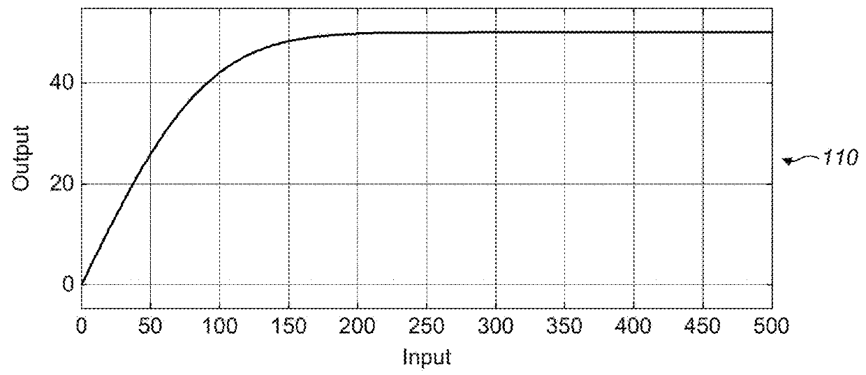
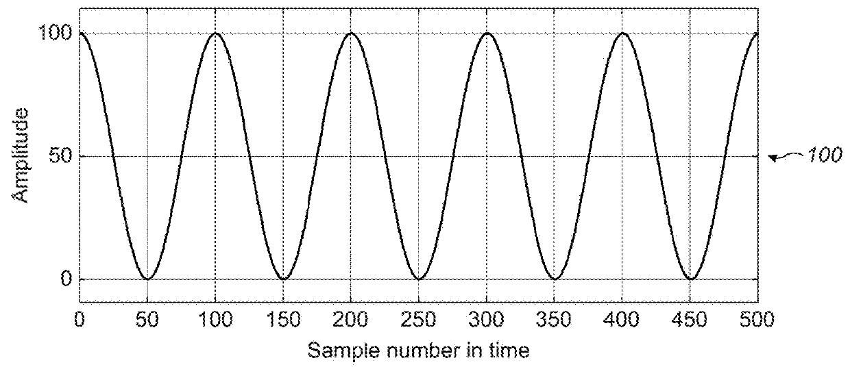
physical limitations of the playback device, an exact waveform may not be reproducible as specified.
However, due to interactivity and thus low latency being a requirement, only part or even individual samples of the waveform may be available.
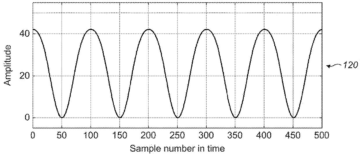
As the waveform can be infinite in amplitude, this does not fill the entire
dynamic range of the output, resulting in unused output range.
The result is that the waveform becomes clipped due to a lack of available power to recreate the necessary amplitude at the
control point.
Unlike a single control point wherein violating the power limitations of the device results in underpowered, clipped waveforms, with multiple control points going over the limitations of the device promotes
crosstalk between the points, muddling their haptic effects.
This results in a reduction in output
dynamic range because the
power budget has been shared unnecessarily between all control points.
The
optimization problem required for levitating particles centers around the use of the Gor'kov energy potential.
However, there are acoustic effects that the Gor'kov potential does not take into account, such as
acoustic streaming wherein the acoustic
waves induce bulk movement in the fluid.
The problem with this is that the cross-terms effectively mean that this becomes:
These are less effective as they do not maximize the objective function.
This means it cannot be solved for the acoustic intensity in a given direction, as it is made up of two independent variables.
However, when using the reduced representation approach to the solution of the
system, that is the specification of the C matrix to reduce the amount of effort required, the number of entries of this matrix increases by a factor of nine, making the problem significantly more intensive to compute.
However, the direction of the resulting wave must be known before the
solver can function and therefore cannot be influenced by the
solver.
However, unfortunately {
circumflex over (n)}j cannot be known a priori, and it is required to construct the
linear system matrix:
As a result, it is impossible for a haptic effect to be imparted.
The largest
disadvantage is that many calculations are required, but the calculations are effectively only complex multiplications which with sufficient hardware are straightforwardly implemented.
It should be noted that this process increases the rank of the matrix, so simplification is not possible should this be used.
This generates a matrix that has increased rank, so some simplification methods are not possible in the case that this is used.
The beam may not be an exact
Bessel beam due to the effects of limited
transducer resolution, finite array size and other physical considerations which the optimization will need to work around, but may perform more effectively than a simple evaluation of a
Bessel beam function due to the optimization taking into account the
physical limitations of a real
transducer array.
This is because the
wavefront direction conveys directional information that is missing from the
particle velocity, the
particle velocity does not yield information pertaining to which direction the wave originated from, enabling unwanted interference.
This is because a particle
velocity vector with complex components cannot determine the difference between
waves travelling in different directions: a wave travelling left-to-right with phase 0 is in this model for a point sample mathematically identical to a right-to-left travelling wave with phase π. As a result, if this is not dealt with correctly in the generation of the control point or region basis, the optimization will attempt to use both, generating a solution with
standing wave components that do not contribute meaningfully, creating extra nulls, regions with no field, that are unwanted.
Hardware division among other difficult to implement functions to pre- and post-
processing steps on the
data input and output.
Irrational values and factors that create
rounding issues for efficient implementations.
This involves a hardware division (the 1994 paper recommends the SRT division technique), and so this adds a highly expensive technique in terms of the logic required to implement a division alongside the algorithm.
This involves yet more division processes that are expensive in terms of logic size.
This is yet more unwanted irrational values, however, if we specifically use the base e2π we can use θ to express the number of rotations.
Unfortunately, using this base leads to a method that does not converge.
This contrasts with the auxiliary multiplication, where the original register could be overloaded, which cannot be achieved here because the modification of the exponentiation register in this mode would prevent convergence of the algorithm.
However, using auxiliary registers can circumvent this, allowing the logarithm process to, if desired, produce complex-valued division of almost arbitrarily many other complex values with the value input to this process as denominator.
The drawback of this is that the choices for the look-up tables and shifts would also have to be merged, creating a larger set of choices for the algorithm to work through per iteration.
It should be noted that this process increases the rank of the matrix, so simplification is not possible should this be used.
This generates a matrix that has increased rank, so some simplification methods are not possible in the case that this is used.
This is due to the fact that the matrix may no longer be Hermitian and therefore the direct application of the Rayleigh-Ritz method to this matrix without completing the above step may cause the method to fail to converge to the dominant eigenvector.

