X-ray phase imaging apparatus

a phase imaging and phase detection technology, applied in the direction of radiation diagnostic diaphragms, instruments, radiation generation arrangements, etc., can solve the problems of phase differential image phase folding and error in measured values, and achieve the effect of shortening the image extraction time, increasing the intensity of x-ray irradiation from the x-ray source, and facilitating the relative position of the plurality

Active Publication Date: 2018-06-21
SHIMADZU CORP
View PDF5 Cites 2 Cited by
  • Summary
  • Abstract
  • Description
  • Claims
  • Application Information

AI Technical Summary

Benefits of technology

[0017]In the X-ray phase imaging apparatus according to the first aspect, it is preferable that the plurality of gratings further include a third grating provided between the X-ray source and the first grating. With this configuration, by micro-focusing the X-ray irradiated from the X-ray source using the third grating, it becomes unnecessary to use a micro-focus X-ray source to form a self-image of the first grating. Therefore, it becomes possible to use an X-ray source with high X-ray intensity which cannot be obtained with a micro-focus X-ray source. As a result, the intensity of the X-ray irradiated from the X-ray source increases, which can shorten the image extraction time.
[0018]In the X-ray phase imaging apparatus according to the first aspect, it is preferable to further include a moving mechanism configured to move at least any one of the plurality of gratings to change the intensity of the X-ray detected by the detection unit. With such a configuration, it is possible to easily change the relative positions of the plurality of gratings.
[0019]In the configuration in which the X-ray phase imaging apparatus includes the moving mechanism, it is preferably configured such that the moving mechanism moves at least any one of the plurality of gratings to correct the displacement amount. With this configuration, for example, in the case of moving the grating by the moving mechanism to generate an image, a moving mechanism for imaging and a moving mechanism for correcting a displacement can be used in common. Thus, the configuration of the apparatus can be simplified and the number of parts can be reduced.
[0020]In the configuration in which the X-ray phase imaging apparatus includes the moving mechanism, it is preferably configured such that the moving mechanism corrects the displacement amount by moving the grating having a maximum grating pitch among the plurality of gratings. With this configuration, since the displacement amount is proportional to the grating pitch of the grating, when correcting with wide grating of a grating pitch, the displacement amount increases as compared with the case in which correction is performed with narrow grating of a grating pitch. As a result, since the distance for moving the moving mechanism to correct the displacement amount increases, the displacement amount can be performed easily.
[0021]In the configuration in which the X-ray phase imaging apparatus includes the moving mechanism, it is preferably configured such that the displacement amount is corrected by moving the grating moved to generate the image among the plurality of gratings by the moving mechanism. With this configuration, it is sufficient to move only a specific grating among a plurality of gratings, and therefore the grating movement by the moving mechanism can be easily performed.
[0022]In the X-ray phase imaging apparatus according to the first aspect, it is preferably configured such that the X-ray phase imaging apparatus further includes a rotation mechanism configured to relatively rotate an imaging system and the object, the imaging system including the X-ray source, the plurality of gratings, and the detection unit, wherein a tomographic image of the object is captured by relative rotating the imaging system and the object by the rotation mechanism. In this way, in the case of capturing the tomographic image of the object, since the image capturing time becomes long and the relative position of the grating is likely to be displaced, the X-ray phase imaging apparatus which can suppress an occurrence of phase folding in an image is preferable.

Problems solved by technology

When this phase folding occurs, for example, even if the phase-contrast due to the object is (3 / 2)π, it cannot be distinguished from the case where the phase-contrast is −(½)π, which results in an erroneous measured value.
As described above, in the X-ray imaging apparatus as disclosed in the aforementioned patent document, there is a problem that phase folding occurs in the phase differential image due to positional displacements of gratings caused by the influence of heat.

Method used


Image

  • X-ray phase imaging apparatus
  • X-ray phase imaging apparatus
  • X-ray phase imaging apparatus

Examples


first embodiment

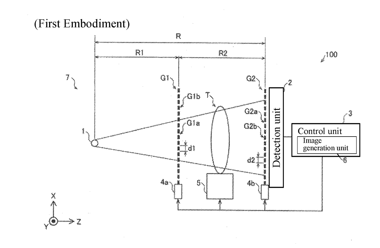
[0034]With reference to FIG. 1, a configuration of an X-ray phase-contrast imaging apparatus 100 according to a first embodiment of the present invention will be described. The X-ray phase-contrast imaging apparatus 100 is an example of the “X-ray phase imaging apparatus” recited in claims.

[0035]As shown in FIG. 1, the X-ray phase-contrast imaging apparatus 100 is an apparatus for imaging an inside of an object T by using the phase-contrast of the X-ray that passed through the object T. The X-ray phase-contrast imaging apparatus 100 is an apparatus for imaging the inside of the object T utilizing the Talbot effect.

(Configuration of X-Ray Phase-Contrast Imaging Apparatus)

[0036]As shown in FIG. 1, the X-ray phase-contrast imaging apparatus 100 is equipped with an X-ray source 1, a phase grating G1, an absorption grating G2, a detection unit 2, a control unit 3, grating moving stages 4a and 4b, and an object rotation stage 5. In the X-ray phase-contrast imaging apparatus 100, the X-ray...

second embodiment

[0085]Next, a second embodiment will be described with reference to FIG. 8. In the second embodiment, in addition to the configuration of the first embodiment, a multi-slit G3 is further provided between the X-ray source 1 and the phase grating G1. The same configurations as those of the first embodiment are denoted by the same reference numerals in the drawings, and description thereof will be omitted.

(Configuration of X-Ray Phase Contrast Imaging Apparatus)

[0086]The X-ray phase-contrast imaging apparatus 200 according to the second embodiment of the present invention includes a multi slit G3 and a grating moving stage 4c in addition to the configuration of the X-ray phase-contrast imaging apparatus 100 of the first embodiment. Further, in the X-ray phase-contrast imaging apparatus 200, the X-ray source 11 is an X-ray source with higher power than the X-ray source 1 of the X-ray phase-contrast imaging apparatus 100 of the first embodiment. Note that the X-ray phase-contrast imaging...

modified examples

[0098]It should be understood that the embodiments disclosed here are examples in all respects and are not restrictive. The scope of the present invention is shown by the scope of the claims rather than the descriptions of the embodiments described above, and includes all modifications (modified examples) within the meaning of equivalent and the scope of claims.

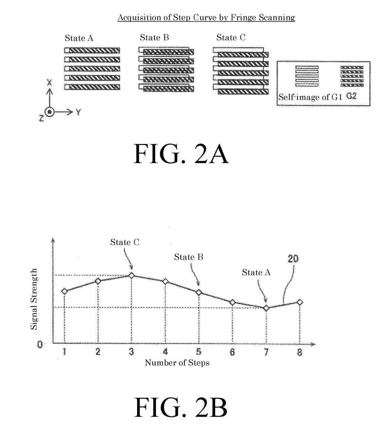
[0099]In the first and second embodiments, based on the step curve 21 of the AIR image 40, the displacement amounts of a plurality of grating relative positions are corrected based on the phase-contrast Δφ with the step curve 22 of the object captured image 41, but the present invention is not limited to this. In the present invention, on the basis of the step curve 22 of the object captured image 41, the displacement amounts of a plurality of grating relative positions may be corrected based on the phase-contrast Δφ of the step curve 22 of the object captured image 41 and the step curve 22 of the object captured image 41.

[01...


PUM

PropertyMeasurementUnit
displacementaaaaaaaaaa
phase-contrastaaaaaaaaaa
phase differential imageaaaaaaaaaa

Abstract

The X-ray phase imaging apparatus is configured to include an image generation unit that generates an X-ray phase-contrast image based on a phase-contrast between a step curve representing an intensity change of an X-ray when an object is placed between an X-ray source and a phase grating or between a phase grating and an absorption grating and a step curve when no object is placed therebetween, and is configured to obtain a displacement amount of relative positions of a plurality of gratings based on a plurality of step curves.

Description

CROSS-REFERENCE TO RELATED APPLICATIONS[0001]The present application claims priority to Japanese Patent Application No. 2016-246689, entitled “X-ray Phase Imaging Apparatus”, filed on Dec. 20, 2016, and invented by Satoshi Sano, Taro Shirai, Takahiro Doki, and Akira Horiba, the disclosure of which is incorporated by reference in its entirety.FIELD OF THE INVENTION[0002]The present invention relates to an X-ray phase imaging apparatus.BACKGROUND TECHNIQUE[0003]Conventionally, an X-ray imaging apparatus (X-ray phase imaging apparatus) for imaging an inside of an object utilizing a phase-contrast of an X-ray that passed through the object is known. Such an X-ray imaging apparatus is disclosed, for example, in Japanese Unexamined Patent Application Publication No. 2012-16370.[0004]The X-ray imaging apparatus disclosed in the aforementioned Japanese Unexamined Patent Application Publication No. 2012-16370 includes an X-ray source, an X-ray image detector (detection unit) arranged in the ...

Claims


Application Information

Patent Timeline
Patent Type & Authority Applications(United States)
IPC IPC(8): G01N23/04G01N23/207G21K1/06
CPCG01N23/046G01N23/207G21K1/067G01N2223/419A61B6/06A61B6/40A61B6/42A61B6/4429G01N23/041G21K2207/005G21K1/025G21K1/06A61B6/4035A61B6/4291
Inventor SANO, SATOSHISHIRAI, TARODOKI, TAKAHIROHORIBA, AKIRA
Owner SHIMADZU CORP
Why Eureka
Try Eureka