Apparatus for radiometric correction and orthorectification of aerial imagery

a technology of aerial imagery and radiometric correction, applied in the field of aerial imagery apparatus for radiometric correction and orthorectification, can solve the problems of insufficient calibration, limited ability to account for illumination, and the need to transform images to real-world coordinates, and achieve the effect of enhancing harvest yield and less expensiv

Active Publication Date: 2018-06-28
ARABLE LABS INC
View PDF6 Cites 18 Cited by
  • Summary
  • Abstract
  • Description
  • Claims
  • Application Information

AI Technical Summary

Benefits of technology

[0011]The present inventors have developed a ground-based station that can be used for both orthorectification and radiometric correction of imagery collected by piloted or non-piloted craft. The present inventors have developed a device that combines radiometric readings with light sensors in particular spectral bands, and with GPS readings that can be used for post-flight image processing. In various configurations, a series of images or a “movie” can be generated without flickering in terms of the brightness. In various configurations, a station of the present teachings allows imagery to be corrected in a remote and automated fashion by retrospectively retrieving radiometric and positional data collected by die station at the time of vehicle overpass, without a need for personnel in the field to collect such measurements

Problems solved by technology

One issue with remotely sensed imagery (RSI) as it is conventionally measured, is that observations are not calibrated into reflectances, wherein reflectance is the ratio of upwelling to downwelling radiation within a defined spectral hand.
In the absence of such calibration, there is limited ability to account for the illumination conditions at the time and place of measurement.
A second issue with RSI is the need to transform images to real-world coordinates.
Second, to be comparable over time, raw radiance measurements need radiometric correction for conversion into reflectances.
Thus, in the absence of a measurement of the illumination conditions at the time and place of measurement, there are no means to normalize upwelling radiance into a reflectance product.
This compromises the interpretation of the digital value, because it loses the capacity to be compared with other sites

Method used


Image

  • Apparatus for radiometric correction and orthorectification of aerial imagery
  • Apparatus for radiometric correction and orthorectification of aerial imagery
  • Apparatus for radiometric correction and orthorectification of aerial imagery

Examples


example 1

[0041]Three white ground stations of the present teachings are installed in a farmer's field in San Louis Obispo, Calif. (in the Northern hemisphere) and record continuous readings of upwelling and downwelling radiation data while a camera mounted in a drone collects remotely sensed imagery (RSI). The RSI includes standard RGB color images. Data collected by the devices and the RSI images are downloaded to a remote server located in a drone control center. The radiometric data (in the form of digital numbers, 8-bits for each channel) are then processed into reflectance measurements (FIG. 2): For each ground station, the pixels in the RSI that contain the device are identified by searching for the white ground stations amongst the green in the field (FIG. 3, left). The identification of the ground stations is accelerated using prior knowledge of their coordinates (FIG. 3, right), along with GPS metadata embedded in the image, to localize the search area within the RSI. Additionally, ...

example 2

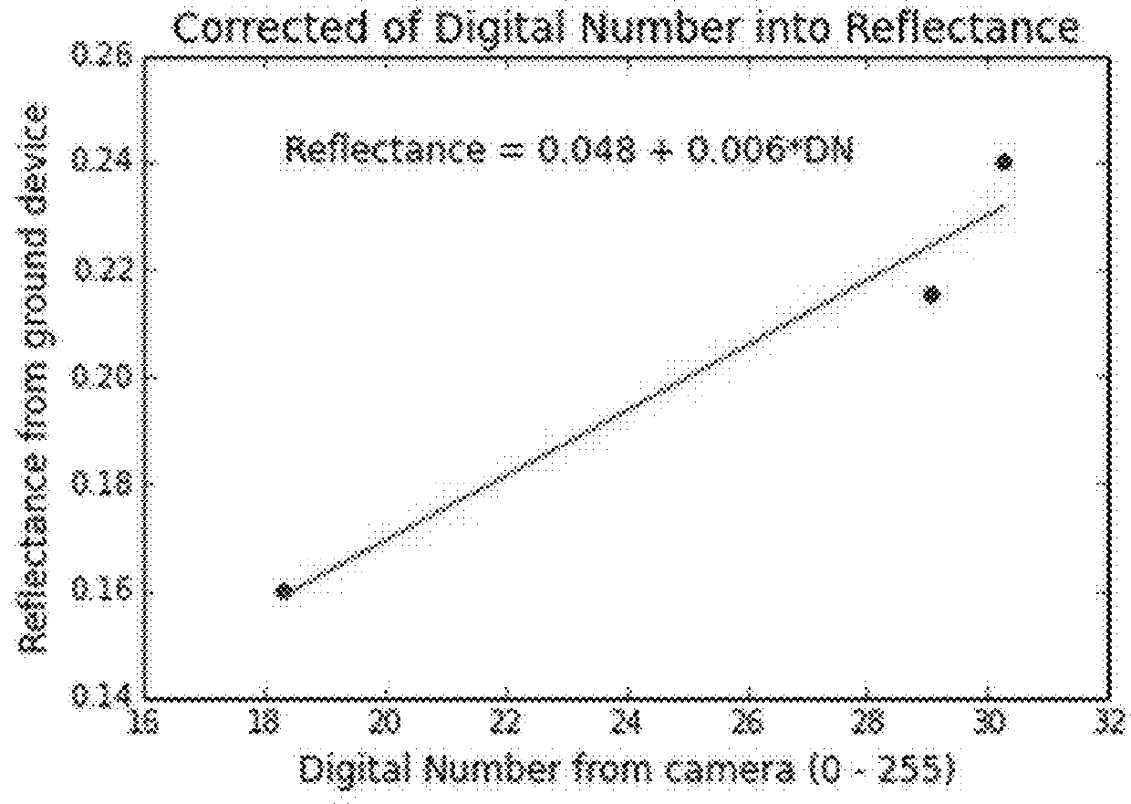
[0043]Five ground stations of the present teachings are installed in a farmer's field in. Australia (in the Southern hemisphere) and record continuous readings of upwelling and down welling radiation collect digital numbers of 8 bits, per color channel while a drone collects remotely sensed imagery (RSI). The RSI includes standard false color infrared (NIR-R-G) images. Data collected by the devices and the RSI images are downloaded to a remote server. A regression analysis between the radiance data from the drone and the reflectance data from each ground station is performed. The equation Reflectance=0.37+0.004*DN, calculated from this linear regression, is used, using pixels from the Northern side of the device to avoid shadows. A pixel near one of the ground stations has an upwelling radiance of 27, and its reflectance is calculated using 0.37+0.004*27=0.478. The pixels in the RSI that contain the device are identified by its distinct spectral signature, and mosaicked RSI are tran...

example 3

[0044]A cranberry farm manager in New Jersey hires a drone operator to take aerial photographs for a growing season, using a sensor that records thermal images. Several ground stations (numbered one through seven) of the present teachings are installed in the field. The position, radiance and irradiance along with infrared thermometer readings are pushed to a database over a cellular network. The drone operator provides the imagery to the client via a web interface. The farm manager logs in securely to the database, and calculates the difference between the temperature calculated from the infrared thermometer readings collected by the ground station and the temperature for the same location measured in the drone-collected imagery. The RSI reading at Ground Station One's pixel is 22.6° C. while the ground station infrared thermometer has a reading of 23.2° C. at the time of image capture, so the difference is 0.6° C. and adjusts the thermal image by this difference using equation: Ca...


PUM


Abstract

The present inventors have developed a ground station that, when installed in a field, can collect upwelling and downwelling radiation, and GPS location coordinates, Data from remotely sensed imagery (RSI) can he used to monitor crop health. Use of the ground station can obviate the need for personnel to he deployed into the field during drone overflights for management of agriculture.

Description

CROSS REFERENCE TO RELATED APPLICATION[0001]This application claims benefit of and priority to Provisional Application 62 / 237,679 filed on Oct. 6, 2015. This application is hereby incorporated by reference in its entirety.INTRODUCTION[0002]Monitoring of the health of a crop is an important component in the scientific management of agriculture. While measurements of ambient weather conditions are strong correlates to yield, measurements of the plants themselves are potentially more diagnostic for problems, and predictive of eventual yield. Often, the health of plants in a field is measured using imagery in particular diagnostic wavelengths collected by satellite, airplane, and unmanned aerial vehicles (UAVs). One issue with remotely sensed imagery (RSI) as it is conventionally measured, is that observations are not calibrated into reflectances, wherein reflectance is the ratio of upwelling to downwelling radiation within a defined spectral hand. In the absence of such calibration, th...

Claims


Application Information

Patent Timeline
IPC IPC(8): G01W1/02G01W1/12G01W1/08G01W1/14G06T7/70
CPCG01W1/02G01W1/12G01W1/08G01W1/14G06T7/70G01N33/246G01N2033/245G01N33/0098G06T2207/10036G06T2207/30188G01J3/00
Inventor WOLF, ADAMDUFFY, BRENDENESTES, LYNDON
Owner ARABLE LABS INC
Why Eureka
Try Eureka