Device for generating an ultrasonic vibration of a tool and for measuring vibration parameters

a technology of ultrasonic vibration and tool, which is applied in the direction of manufacturing tools, instruments, chucks, etc., can solve the problems of temperature drift of resonance frequency, less efficient processing operation, and change in resonance frequency, so as to reduce the amplitude

Active Publication Date: 2018-07-12
SAUER GMBH
View PDF2 Cites 7 Cited by
  • Summary
  • Abstract
  • Description
  • Claims
  • Application Information

AI Technical Summary

Benefits of technology

[0022]In particular, an object of the present invention is to provide a device by means of which a higher processing accuracy can be achieved in the ultrasonic machining of a workpiece.
[0059]Therefore, resonance frequency changes in the vibratory system and / or a reduction in the amplitude can easily be determined from the sensor signal. Thus, the vibration system can be adjusted in resonance on the basis of the comparison of the radiated frequency and the current resonance frequency if this is advantageous for the processing operation.

Problems solved by technology

This causes the problem that the resonance frequency can change in the course of a processing operation.
This changes the properties of the material and leads to a temperature drift of the resonance frequency.
If the free resonance frequency is used for the stimulation, but the actual resonance frequency of the system differs therefrom during processing, the vibration of the tool has a smaller amplitude, and therefore the processing operation becomes less efficient.
However, this method is not suitable for a machining operation because, unlike ultrasonic welding, the impedance curves of the utilized sonotrodes with inserted tools are much more complex: On the one hand, there are significantly more impedance minimums due to the many different vibration modes of the tools which have complex forms.
In contrast, the frequency shift constantly changes during machining on account of varying engaging conditions of the tool into the material and, as described above, the assignment is often no longer possible by means of an impedance measurement alone.
This is because a great many tools with different forms are used, e.g. drills and milling cutters having different dimensions and cutting tools having different cutting edge geometries, which leads to a higher variance in the shape of the impedance curve as compared to ultrasonic welding.
In addition, on account of the recurring processing steps during welding the dominating frequency shift effect can be well predicted, which limits the possible reactions of the system.
In contrast, all effects have to be taken into consideration in a machining operation, and for this reason the prediction possibilities and / or the possibilities for limiting the adjustment parameters are insufficient.
Moreover, it is not possible to distinguish bending vibrations or the like from axial vibration modes on the basis of the impedance measurement alone.
These parasitic effects cannot be detected by the known methods.

Method used


Image

  • Device for generating an ultrasonic vibration of a tool and for measuring vibration parameters
  • Device for generating an ultrasonic vibration of a tool and for measuring vibration parameters
  • Device for generating an ultrasonic vibration of a tool and for measuring vibration parameters

Examples


Embodiment Construction

[0069]The present invention is described and explained in detail below by means of embodiments and the exemplary drawings.

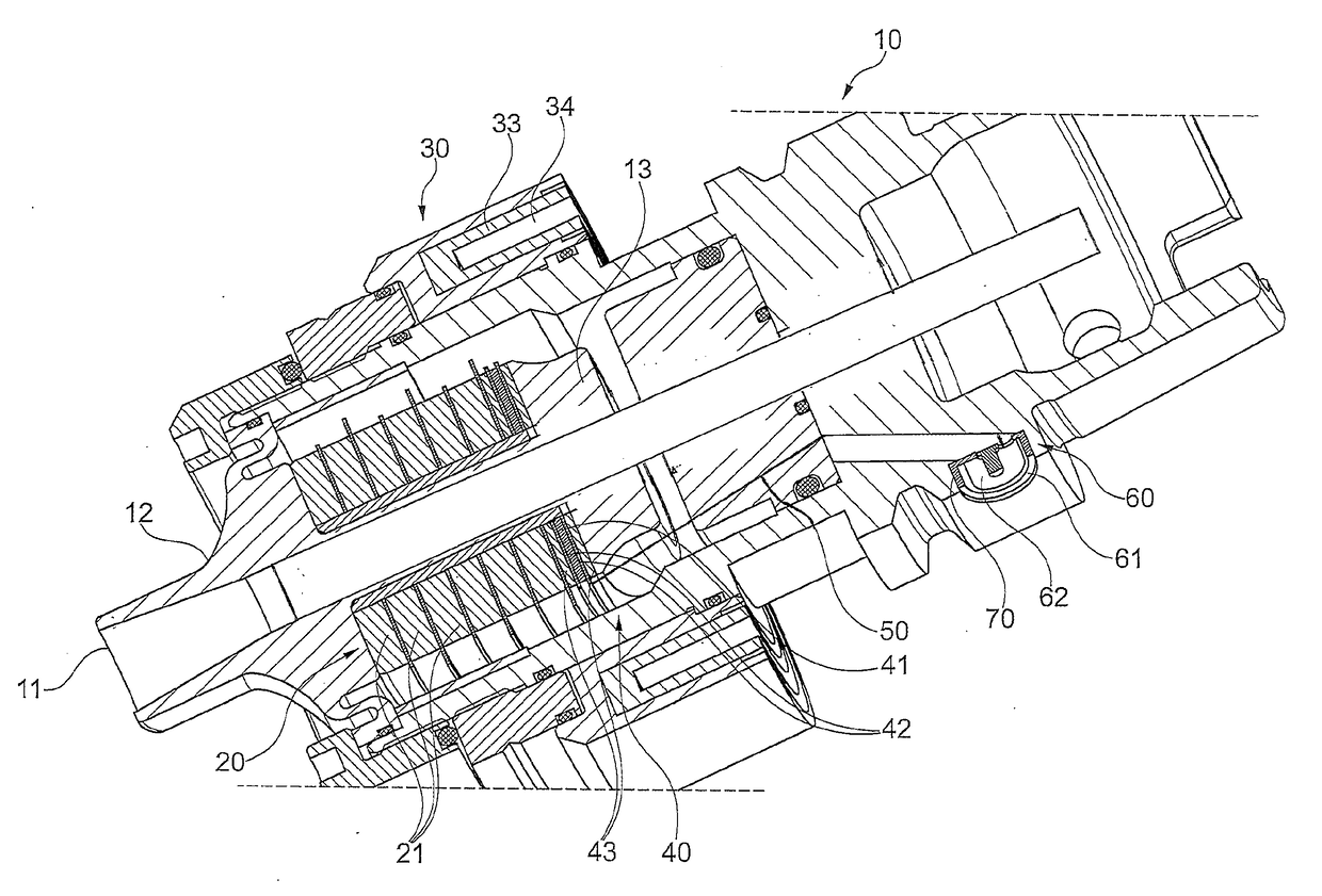
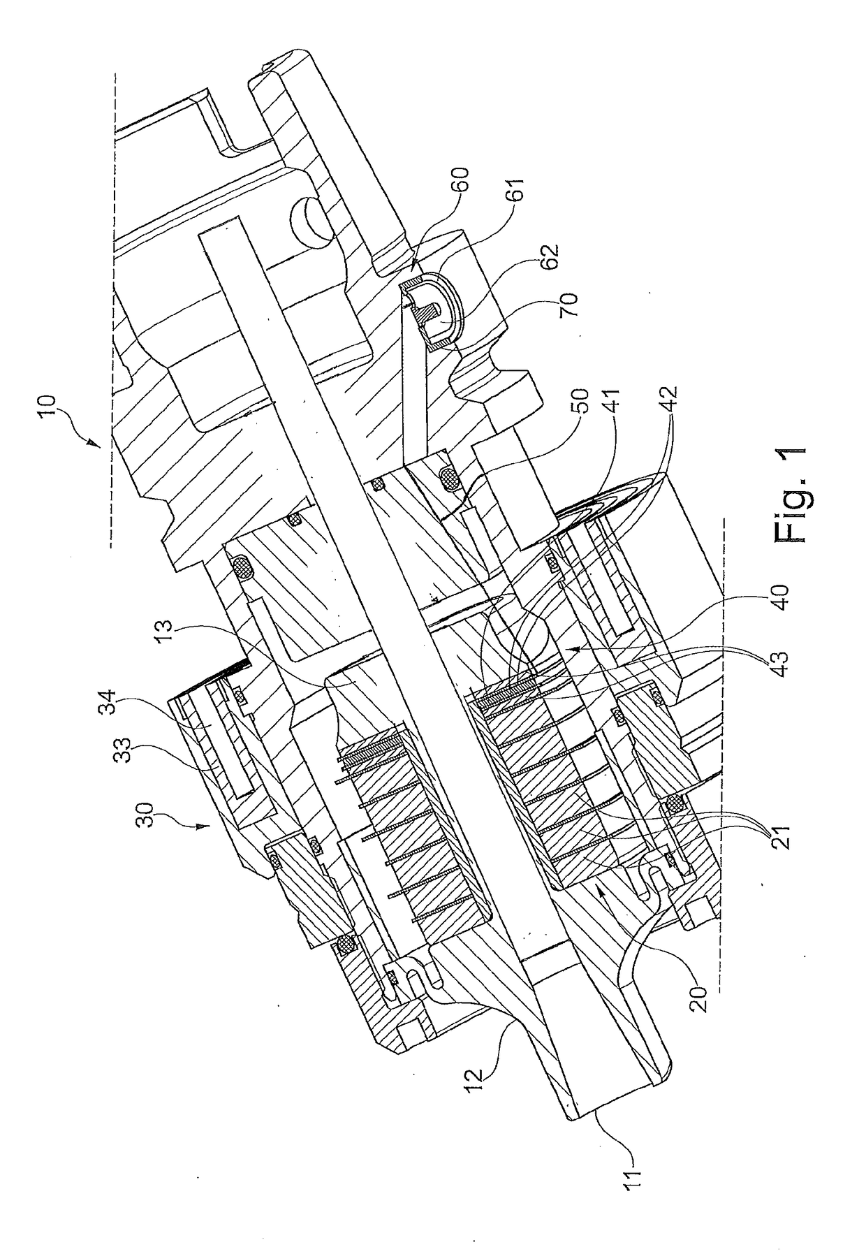
[0070]FIG. 1 shows a tool holder 10 of a device according to the invention. A tool support portion 11 for receiving a tool 90 (not shown) is disposed on one end of the tool holder 10. A plurality, e.g. six, perforated disk-shaped first piezo elements 21 are arranged in stacked fashion in the tool holder 10. Said piezo elements are connected to the tool support portion 11 via a transmission portion 12 and form an ultrasonic transducer 20 for converting an electric voltage into a mechanical vibration. The mechanical vibration of the first piezo elements 21 is transmitted to the tool 90 via the transmission portion 12. The first piezo elements 21 can be designed e.g. as piezo ceramic disks with electrodes mounted between them. The power is supplied to the ultrasonic transducer 20 via a transformer (second transformer) which, on the machine side, consists of a first ...


PUM

PropertyMeasurementUnit
ultrasonic vibration parametersaaaaaaaaaa
ultrasonic vibrationaaaaaaaaaa
electric voltageaaaaaaaaaa

Abstract

The present invention relates to a device for generating an ultrasonic vibration of a tool used for the ultrasonic machining of a workpiece and for measuring ultrasonic vibration parameters of the ultrasonic vibration of the tool having a tool holder for receiving the tool, an ultrasonic transducer in the tool holder for generating the ultrasonic vibration of the tool, a sensor mechanism in the tool holder for producing a sensor signal on the basis of the ultrasonic vibration of the tool, and a sensor signal evaluation device for evaluating the sensor signal.

Description

TECHNICAL FIELD[0001]The present invention relates to a device for generating an ultrasonic vibration of a tool for the ultrasonic machining of a workpiece and for measuring ultrasonic vibration parameters of the ultrasonic vibration of the tool with a tool holder for receiving the tool and an ultrasonic transducer in the tool holder for generating the ultrasonic vibration of the tool and a method for measuring ultrasonic vibration parameters of a tool for the ultrasonic machining of a workpiece.BACKGROUND OF THE INVENTION[0002]The prior art discloses machine tools for machining workpieces, which have a signal processing unit and transmitter and receiver diodes in the tool holder, by means of which signals can be transmitted to a transmitting and receiving station.[0003]EP 0 229 399 A2 describes in this connection a chuck having a number of transmitter diodes and receiver diodes, arranged in a radial plane at peripheral distances, and a signal processing unit which is installed in t...

Claims


Application Information

Patent Timeline
Patent Type & Authority Applications(United States)
IPC IPC(8): B23B31/10B23B37/00B24B1/04
CPCB23B31/10B23B37/00B24B1/04B23B2260/108B23B2260/1285B23B2270/10B23C2270/10B23B2260/128G01H11/08
Inventor KETELAER, JENS
Owner SAUER GMBH
Why Eureka
Try Eureka