System and method for reduced-speckle laser line generation

Active Publication Date: 2018-07-19
COGNEX CORPORATION
View PDF6 Cites 23 Cited by
  • Summary
  • Abstract
  • Description
  • Claims
  • Application Information

AI Technical Summary

Benefits of technology

[0007]This invention overcomes disadvantages of prior art by providing a coherent light (laser) beam that moves (e.g. laterally), in a (e.g.) cyclic manner, across a stationary line generator (e.g. a linear diffuser, hologram or other diffractive element, and/or cylinder array). This allows the local phase of the line pattern projected through the diffuser onto the surface to change significantly faster, as a relatively small mass is cycled to redirect the beam using a moving mirror structure—for example using a MEMS mirror, or another arrangement that is free of a moving mass, such as solid state beam deflector (e.g. an AOM). This arrangement allows for relatively short exposure times since the projected phase, and thus, imaged speckle pattern varies at a high rate. The use of a linear diffuser allows for a high quality line that is generally free of diffusion and/or broadening (in thickness) in the direction substantially perpendicular to the line's axis (the line's thickness). In an embodiment in which an image sensor

Problems solved by technology

However, speckle patterns are inherent in coherent light sources, such as lasers.
Speckle can be problematic in certain imaging applications—for example a laser displacement sensor (DS), which projects a laser line (based on a fan formed (e.g.) by passing a laser beam through an aspherical lens (such as a Powell lens or another appropriate generator including cylinder lenses, holographic, cylinder arrays, linear diffusers, or combinations thereof) onto a surface, and receives the reflected light at a camera sensor along a camera axis that is not parallel to the axis of the laser fan.
However, the lumpy and asymmetric irregularity of the received line light, as a result of speckle, limits the precision of the location of the line by the came

Method used


Image

  • System and method for reduced-speckle laser line generation
  • System and method for reduced-speckle laser line generation
  • System and method for reduced-speckle laser line generation

Examples


Example

I. Vision System Implementation

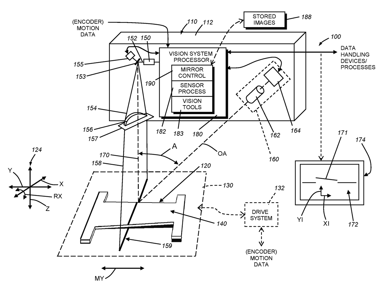
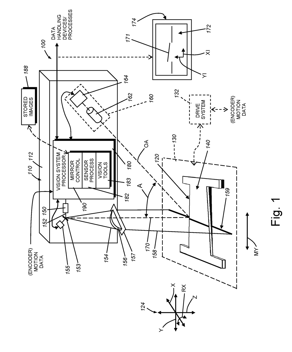
[0029]By way of non-limiting example, FIG. 1 shows a vision system arrangement 100 including a laser displacement sensor (DS) assembly 110 oriented to image an object 120 (also sometimes referred to as a “part”). The DS assembly 110 can be contained in a single housing 112 that is mounted at an appropriate location with respect to the imaged scene. In alternate embodiments, the displacement sensor can comprise discrete, separated subcomponents. In an exemplary implementation, the object 120 and the displacement sensor 110 are in relative motion (double arrow MY) with either the displacement sensor 110, the object 120, or both, moving (the scan motion direction) along at least one axis of the relative coordinate system 124 (in this example, the physical y-axis direction). In a typical arrangement, the object 120 is located on a motion conveyance 130 (shown in phantom) that provides motion data from an encoder or similar device operatively connected to t...


PUM


Abstract

A coherent beam moves across a stationary line generator, allowing the speckle pattern projected through the diffuser onto the surface—for example using a MEMS mirror, or another arrangement that is free of a moving mass, such as solid state beam deflector (e.g. an AOM). Where an image sensor is employed, such as a DS, the beam is moved at a speed of at least ½ cycle per image frame so that the full length of the line within the imaged scene is captured by the image sensor. The distance traversed on the diffuser provides sufficient uncorrelated speckle patterns within an exposure time to average to a smooth line. The MEMS mirror can be arranged to oscillate in two substantially orthogonal degrees of freedom so that the line is generated along a first direction and the line moves along the working surface in a second direction.

Description

RELATED APPLICATION[0001]This application claims the benefit of co-pending U.S. Provisional Application Ser. No. 62 / 448,250, entitled SYSTEM AND METHOD FOR REDUCED-SPECKLE LASER LINE GENERATION, filed Jan. 19, 2017, the teachings of which are expressly incorporated herein by reference.FIELD OF THE INVENTION[0002]This invention relates to laser line generation and projection systems, devices and methods, and more particularly to laser line generation and projection systems, devices and methods that can be used in three-dimensional (3D) machine vision systems.BACKGROUND OF THE INVENTION[0003]Speckle is a phenomenon that affects all lasers and laser line projectors. It is caused by the roughness of the surface that is illuminated causing tiny diffractive regions that give the surface a grainy random “speckle” appearance. The speckle effect is a result of the interference of many waves of the same frequency, having different phases and amplitudes, which add together coherently to give a...

Claims


Application Information

Patent Timeline
IPC IPC(8): G02B27/48G01B11/14G02B27/30G02B26/10H04N13/02
CPCG02B27/48G01B11/14H04N13/254G02B27/30G02B26/105G02B27/0927G02B27/0938G02B27/0966G01B11/02G01B11/2518G01B11/2522G02B5/0252G02B5/0257
Inventor FILHABER, JOHN F.
Owner COGNEX CORPORATION
Why Eureka
Try Eureka