Cable fitting for connecting a high-voltage cable to a high-voltage component

a high-voltage component and cable fitting technology, which is applied in the direction of cable terminations, insulated conductors, cables, etc., can solve the problems of limiting the maximum electric current rating of the known cable end termination, affecting and affecting the safety of the environment, so as to facilitate the mounting of the high-voltage current terminal and the effect of dissipation of hea

Active Publication Date: 2018-08-02
HITACHI ENERGY SWITZERLAND AG
View PDF48 Cites 5 Cited by
  • Summary
  • Abstract
  • Description
  • Claims
  • Application Information

AI Technical Summary

Benefits of technology

[0016]The cable fitting according to the invention distinguishes over prior art cable fittings with a small electric resistance of the current path which is formed as an uninterrupted cable conductor having a well-defined constant cross-section and running through the condenser core without any electric connection, thus having small ohmic losses and generating small amount of heat. Another advantage is the small diameter of the current path of the cable fitting on the whole length of the condenser core thus allowing for a small diameter of the innermost field-grading layer and, in consequence, a small diameter of the whole condenser core. This allows for manufacturing the condenser core using less amount of insulating material and also decreases the radial thermal resistance of the condenser core improving its ability to dissipate heat from the cable conductor running through the condenser core. The small ohmic losses of the current path combined with the large ability to dissipate heat from the current path allow for a significant increase of the current rating of the cable fitting when compared to the known constructions.
[0017]These advantages are particularly beneficial for a cable conductor which is formed as a conductor of segmented type. Such conductors are typically installed in AC cables of highest current ratings and are optimized so that the increase of the AC resistance due to the skin effect is minimized. Hence, the ohmic losses under AC current are also minimized and are much smaller compared to those in a rod or tubular conductors applied in known constructions.
[0018]In a preferred embodiment of a cable fitting according to the invention a gap in the tubular duct between an outer surface of the cable conductor and an inner surface of the condenser core can be filled with a thermally conductive material. An advantage of such an embodiment is the decreased overall radial thermal resistance between the conductor and the outer surface of the cable fitting which leads to a higher heat dissipation rate of the cable fitting and to a higher current rating.
[0020]The condenser core can comprise an electrically conducting central tube which forms an outer surface of the tubular duct, and the high-voltage current terminal can be fixedly secured to a top end of the central tube and can be electrically connected to a free end of the stripped-off section of the cable conductor. The central tube facilitates the mounting of the high-voltage current terminal and at the time favors the dissipation of heat generated in the section of the cable conductor running through the condenser core. The central tube can be connected to an innermost of the plurality of field-grading layers.
[0021]The central tube can run down from the high-voltage current terminal at most to the upper edge of the innermost field-grading layer. The diameter of the innermost field-grading layer then can be made smaller than the outer diameter of the central tube, thus resulting in a smaller overall diameter of the condenser core resp. of the cable fitting.

Problems solved by technology

However, the SF6 gas poses risks related to environmental pollution in case of leakage, whereas the gel-like insulating medium typically comprises a low breakdown strength and thus requires the diameter of the insulator to be very large.
These properties combined with the low thermal conductivity of the materials replacing the filling oil limit the thermal transport of the heat generated in a current path of the cable end termination and thus limit the maximal electric current rating of the known cable end termination.
However, the cable end termination lacks any means for reducing the radial component of the electric field within the rigid insulator.
This makes the external terminal diameter of the cable end termination large and requires large amounts of insulating material for its manufacturing.
Furthermore, the electric resistance of the contact arrangement causes the generation of additional heat.
The ability to evacuate this heat outside of the termination is limited due to the large thickness of the insulation thus, in turn, limiting the maximal current rating of the cable termination.
This again makes the outer diameter of the termination large and at the same times poses strong limitations on the ability to remove heat from the socket-plug contact and from the conductor extension.

Method used


Image

  • Cable fitting for connecting a high-voltage cable to a high-voltage component
  • Cable fitting for connecting a high-voltage cable to a high-voltage component
  • Cable fitting for connecting a high-voltage cable to a high-voltage component

Examples


Embodiment Construction

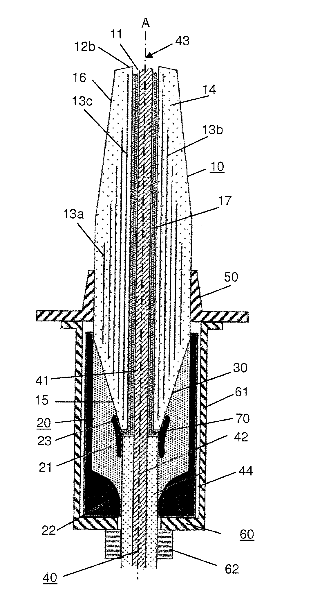
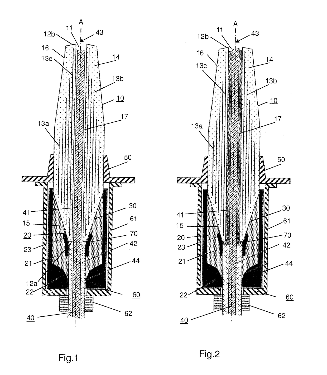
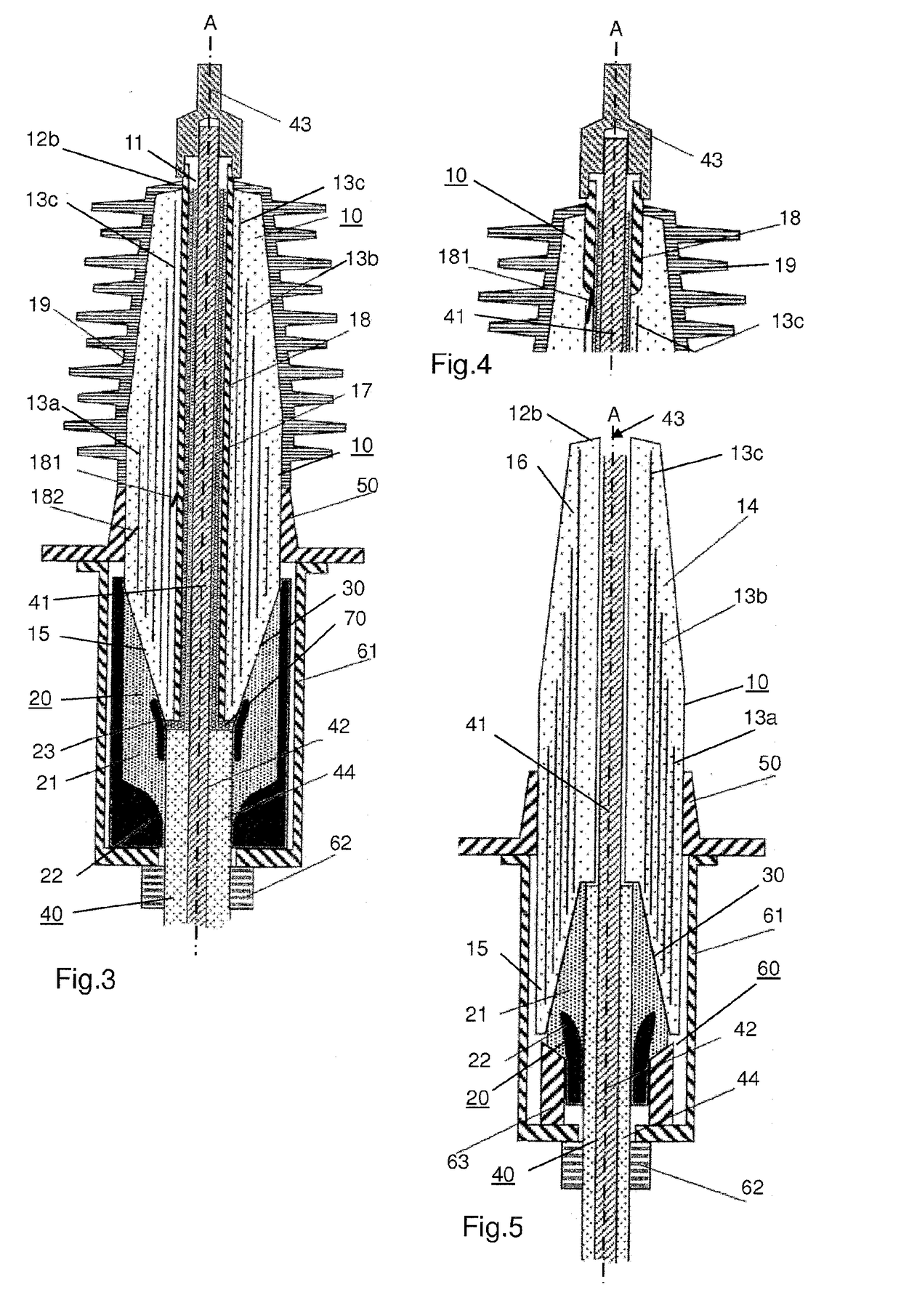
[0014]It is an object of the invention as described in the patent claims to specify a cable fitting of the afore-mentioned type which is small-sized and which at the time is capable to carry high-rated continuous currents.

[0015]The invention supplies a cable fitting for connecting a high-voltage cable having a cable conductor and a cable insulation, which encases the cable conductor, to a high-voltage component. The cable fitting comprises coaxially arranged around an axis a rigid conical insulator, an electrically insulating, elastomeric stress-relief cone matching the rigid conical insulator through a conical interface and an axially aligned current path which connects the cable conductor to a high-voltage current terminal arranged on top of the rigid conical insulator and provided for connection to the high-voltage component. The rigid conical insulator is configured as a condenser core and comprises a plurality of electrically conductive field-grading layers which are arranged c...


PUM

PropertyMeasurementUnit
voltageaaaaaaaaaa
voltageaaaaaaaaaa
voltageaaaaaaaaaa

Abstract

A high-voltage cable fitting, typically a cable end termination or a cable joint, includes coaxially arranged around an axis a rigid conical insulator, an electrically insulating, elastomeric stress-relief cone matching the rigid conical insulator through a conical interface and an axially aligned current path. The current path connects a conductor of the cable to a high-voltage current terminal arranged on top of the rigid conical insulator and provided for connection to a high-voltage component. The rigid conical insulator is configured as a condenser core and includes a plurality of electrically conductive field-grading layers, which are arranged concentrically around the axis, and a rigid polymeric matrix which embeds the field-grading layers. In order to keep the size of the cable fitting small and to enable the fitting to carry high rated continuous currents a section of the cable conductor, which is stripped off the insulation of the cable, extends from the conical interface to the high-voltage current terminal and forms the axially aligned current path, and the condenser core comprises an axially aligned tubular duct which receives the stripped-off section of the cable conductor and which passes two opposing front faces of the condenser core.

Description

TECHNICAL FIELD[0001]The invention relates to a cable fitting for connecting a high-voltage cable to a high-voltage component according to the introductory part of claim 1. Such a cable fitting usually is designed as a cable end termination, in particular as a high-voltage outdoor cable end termination for application in a voltage range from 52 kV up to 1100 kV. The cable end termination can also be designed as a high-voltage indoor cable end termination, typically for a transformer or for a high-voltage gas-insulated switchgear component.[0002]In general the high voltage can range from at least 1 kV to more than 1200 kV. Furthermore the cable fitting is typically designed as a high-voltage cable end termination but can also be designed as a high-voltage cable joint.[0003]Most of the cable fittings are designed as high-voltage outdoor cable end terminations and are made with a hollow-core insulator which is filled with insulating oil. The cable is fixed to a base part of the cable e...

Claims


Application Information

Patent Timeline
Patent Type & Authority Applications(United States)
IPC IPC(8): H02G15/06H01B7/02
CPCH02G15/06H01B7/02H01R11/26H01R4/183H02G15/02H02G15/064H02G15/072
Inventor CZYZEWSKI, JANMAURER, VICTORIALICHY, RADIMSORQVIST, TORBJORN
Owner HITACHI ENERGY SWITZERLAND AG
Why Eureka
Try Eureka