Radiation Residue Scanning Device and System

a scanning device and residue technology, applied in the field of nuclear medicine imaging, can solve the problems of affecting the spatial resolution of images, the difficulty of detecting the energy peak of -rays at 284 kev from the compton plateau, and the prior residue scanning device still has problems, so as to reduce the width of the acquisition window, reduce the number of acquisition windows, and low detection efficiency

Active Publication Date: 2018-08-16
BEIJING EXPLORE TIMESTECH CO LTD
View PDF4 Cites 2 Cited by
  • Summary
  • Abstract
  • Description
  • Claims
  • Application Information

AI Technical Summary

Benefits of technology

[0006]In view of the above, the object of embodiments of the present disclosure is to provide a radiation residue scanning device and system, in which a modification is made to subsequent circuits according to a CZT (Cadmium Zinc Telluride) detector, the modification referring to reducing the width of a acquisition window while increasing the number of the acquisition windows. The provided radiation residue scanning device and system solve the problems of low detection efficiency and poor spatial resolution, increase the detection efficiency of the detector, and improve the spatial resolution of the image.

Problems solved by technology

Moreover, considering that the number of γ-rays at a low energy level of 284 KeV is small and their contribution in the energy spectrum falls within the Compton plateau, it is thus difficult to distinguish the energy peak of the γ-rays at 284 KeV from the Compton plateau.
Thus, by increasing the width of the window, the number of the scattered ineffective γ-rays which are marked as effective γ-rays also increased therealong, which ultimately affects the spatial resolution of the image.
In view of the above, the prior residue scanning device still has the problems of low detection efficiency and poor spatial resolution.

Method used


Image

  • Radiation Residue Scanning Device and System
  • Radiation Residue Scanning Device and System
  • Radiation Residue Scanning Device and System

Examples


first embodiment

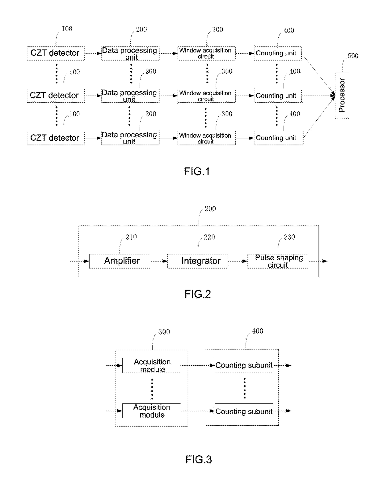
[0042]FIG. 1 is a schematic diagram of the structure of a radiation residue scanning device provided in an embodiment of the present disclosure, and as shown in FIG. 1, the device includes a plurality of CZT (cadmium zinc telluride, CdZnTe) detectors 100, a plurality of data processing units 200, a plurality of window acquisition circuits 300, a plurality of counting units 400, and a processor 500. Specifically, the plurality of CZT detectors 100 are connected in one-to-one correspondence to the plurality of data processing units 200; the plurality of data processing units 200 are connected in one-to-one correspondence to the plurality of window acquisition circuits 300; and the plurality of window acquisition circuits 300 are connected in one-to-one correspondence to the plurality of counting units 400.

[0043]The CZT detector 100 captures γ-rays emitted from a patient's body. The γ-rays release photons and excite electrons by photoelectric effect or Compton effect to form a current ...

second embodiment

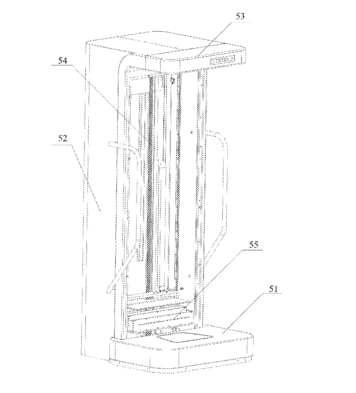
[0057]FIG. 5 shows a schematic diagram of the structure of a radiation residue scanning system provided in an embodiment of the present disclosure. As shown in FIG. 5, the system includes a base 51, a support body, a height measuring device, a lifting device 54, and a radiation residue scanning device 55 as in First Embodiment.

[0058]Here, the base 51 is connected to the support body for bearing a patient in a standing state. The height measuring device is mounted to the support body for measuring the height of the patient. The height measuring device is connected to the processor 500, and the processor 500 receives the above height and determines an initial scanning position and a final scanning position based on the height, and send a driving signal to the lifting device 54.

[0059]Specifically, the radiation residue scanning device 55 can be mounted in the lifting device 54, and the lifting device 54 can be mounted, movably up and down, to the support body, and electrically connecte...


PUM


Abstract

A radiation residue scanning device includes a plurality of CZT detectors, a plurality of data processing units, a plurality of window acquisition circuits, a plurality of counting units, and a processor; the plurality of CZT detectors connected in one-to-one correspondence to the plurality of data processing units; the plurality of data processing units are connected in one-to-one correspondence to the plurality of window acquisition circuits; and the plurality of window acquisition circuits are connected in one-to-one correspondence to the counting units The window acquisition circuit includes a plurality of acquisition modules, and the respective acquisition modules are connected in parallel; the counting unit includes a plurality of counting subunits, the counting subunits are connected in one-to-one correspondence to the acquisition window modules, and the processor is connected to the plurality of counting units.

Description

TECHNICAL FIELD[0001]The present disclosure relates to the technical field of nuclear medicine imaging, and in particular to a radiation (radioactive material) residue scanning device and system.BACKGROUND ART[0002]At present, high-energy elements, for example iodine-131 element, are more and more widely used in nuclear medicine, and especially application of iodine-131 to thyroid diseases, such as diagnostic iodine-131 systemic imaging, post-treatment iodine-131 systemic imaging, removal of residual thyroid tissue after thyroid cancer surgery and treatment of recurrence and metastatic tissue with iodine-131, etc., has a significant effect in treatment with safety and convenience, and is thus a radionuclide therapy project developing most rapidly in China.[0003]A patient treated with iodine-131 needs to be monitored for radiation dose residues for better observation and analysis of the disease condition. At present, an distribution image of iodine-131 in a human body is obtained by ...

Claims


Application Information

Patent Timeline
Patent Type & Authority Applications(United States)
IPC IPC(8): A61B6/00
CPCA61B6/4258A61B6/4266A61B6/545A61B6/4476A61B6/461A61B6/54
Inventor LI, GAOFENG
Owner BEIJING EXPLORE TIMESTECH CO LTD
Why Eureka
Try Eureka