Optical member, and polarizing plate set and liquid crystal display device that use said optical member
- Summary
- Abstract
- Description
- Claims
- Application Information
AI Technical Summary
Benefits of technology
Problems solved by technology
Method used
Image
Examples
example 1
(Wavelength Conversion Material and Prism Sheet)
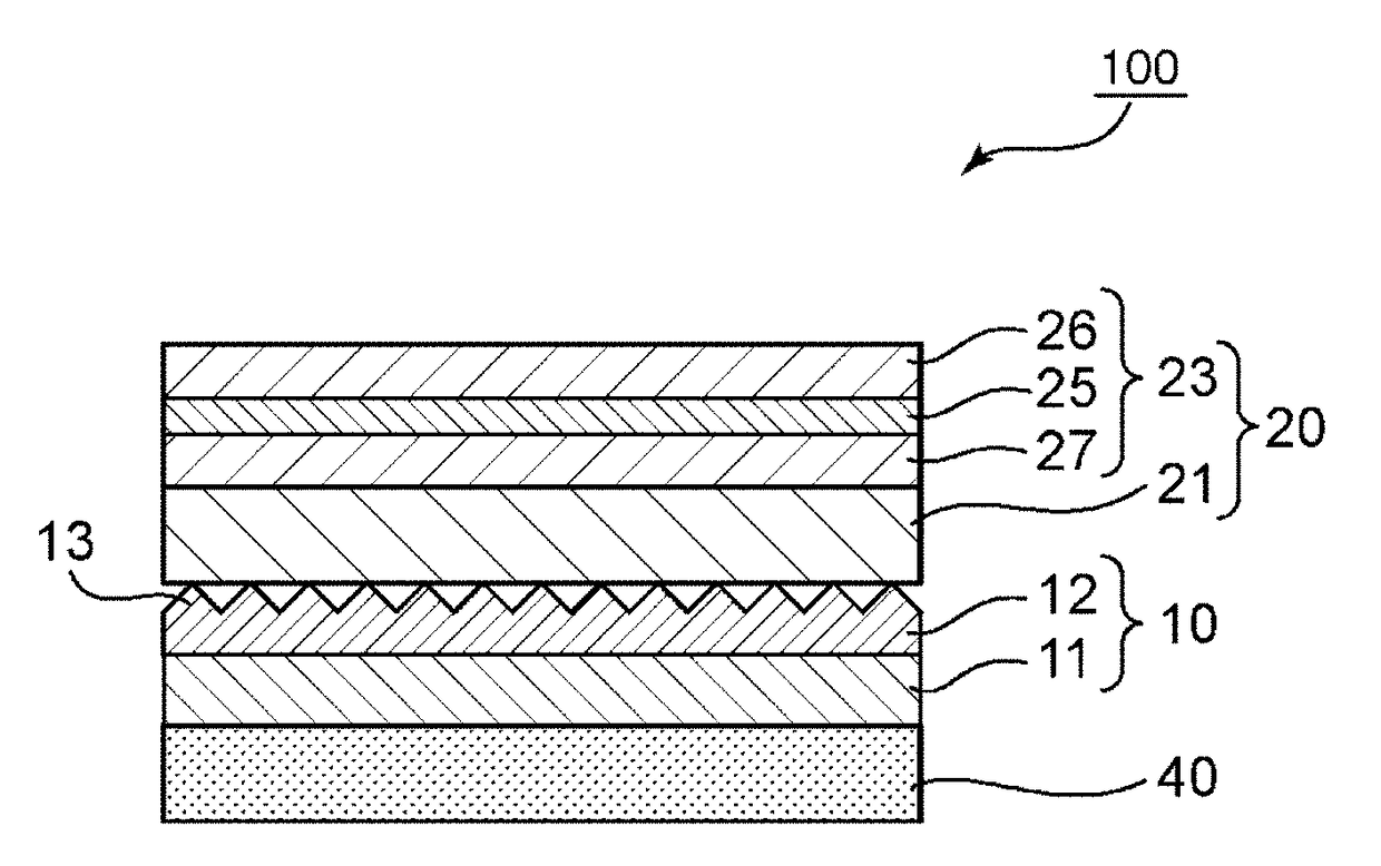
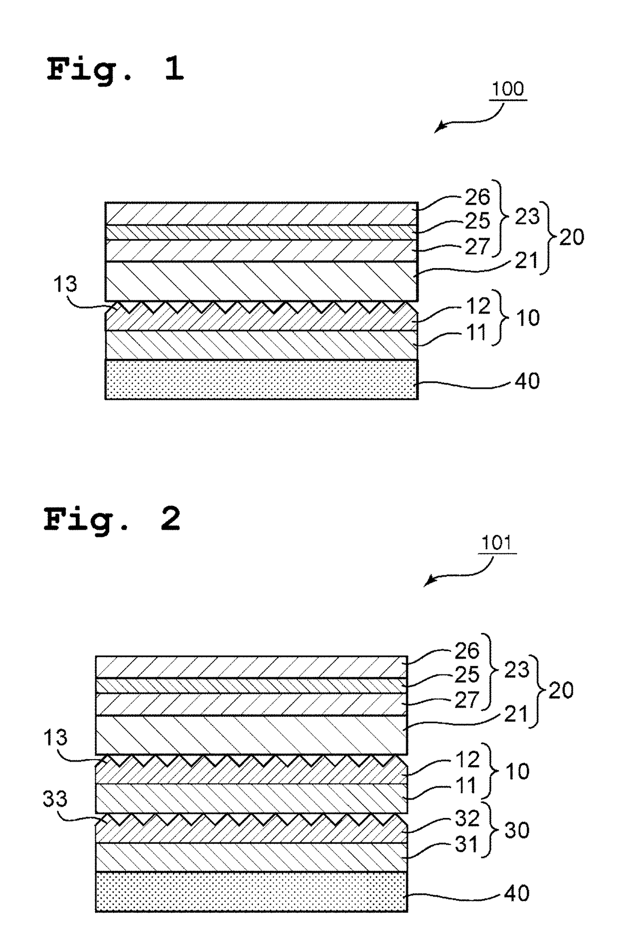
[0161]A commercially available tablet PC (manufactured by Amazon.com, Inc., product name: “Kindle Fire HDX 8.9”) was dismantled, and a wavelength conversion material (wavelength conversion layer) and a prism sheet, which were included on its backlight side, were used.
[0162](Reflective Polarizer)
[0163]A 40-inch TV manufactured by Sharp Corporation (product name: AQUOS, item's stock number: LC40-Z5) was dismantled, and a reflective polarizer was removed from its backlight member. Diffusing layers arranged on both surfaces of the reflective polarizer were removed, and the remainder was defined as a reflective polarizer of this Example.
[0164](Production of Polarizing Plate)
[0165]A polymer film using polyvinyl alcohol as a main component [manufactured by Kuraray Co., Ltd., product name: “9P75R (thickness: 75 μm, average polymerization degree: 2,400, saponification degree: 99.9 mol %)”] was stretched to 1.2 times in its conveying direction w...
example 2
[0171]With the use of two prism sheets, an optical member having a configuration “polarizing plate / reflective polarizer / first prism sheet / second prism sheet” was obtained in the same manner as in Example 1 except that the convex portions of the second prism sheet were subjected to point adhesion to the flat surface of the first prism sheet. A liquid crystal display apparatus was obtained in the same manner as in Example 1 except that this optical member and the wavelength conversion material were incorporated by separate arrangement in the stated order. The resultant liquid crystal display apparatus was subjected to the same evaluation as that in Example 1. The results are shown in Table 1.
example 3
[0172](Formation of Low-refractive Index Layer)
[0173]To a mixed liquid obtained by dissolving 0.95 g of methyltrimethoxysilane (MTMS) serving as a precursor of a silicon compound in 2.2 g of dimethyl sulfoxide (DMSO), 0.5 g of a 0.01 mol / L oxalic acid aqueous solution was added, and the mixture was stirred at room temperature for 30 minutes to hydrolyze the MTMS. Thus, tris(hydroxy)methylsilane was produced. After that, to 5.5 g of DMSO, 0.38 g of ammonia water having a concentration of 28% and 0.2 g of pure water were added, and then the mixed liquid subjected to the hydrolysis treatment was further added. The mixture was stirred at room temperature for 15 minutes to perform gelation of the tris(hydroxy)methylsilane. Thus, a gelled silicon compound was obtained. The mixed liquid subjected to the gelation treatment was subjected to maturation treatment by being incubated as it was at 40° C. for 20 hours. Next, the gelled silicon compound subjected to the maturation treatment was cru...
PUM
 Abstract
Description
Claims
Application Information
 - R&D
- Intellectual Property
- Life Sciences
- Materials
- Tech Scout
- Unparalleled Data Quality
- Higher Quality Content
- 60% Fewer Hallucinations
Browse by: Latest US Patents, China's latest patents, Technical Efficacy Thesaurus, Application Domain, Technology Topic, Popular Technical Reports.
© 2025 PatSnap. All rights reserved.Legal|Privacy policy|Modern Slavery Act Transparency Statement|Sitemap|About US| Contact US: help@patsnap.com


