
Nanomaterial-biomass fiber composite and preparation method thereof

a biomass fiber and nanomaterial technology, applied in the field of composite materials, can solve the problems of low bonding strength, high density, and existing production of binderless fiberboards, and achieve the effect of excellent properties

Inactive Publication Date: 2018-09-13
ZHEJIANG FORESTRY UNIVERSITY
View PDF0 Cites 2 Cited by
  • Summary
  • Abstract
  • Description
  • Claims
  • Application Information

AI Technical Summary

Benefits of technology

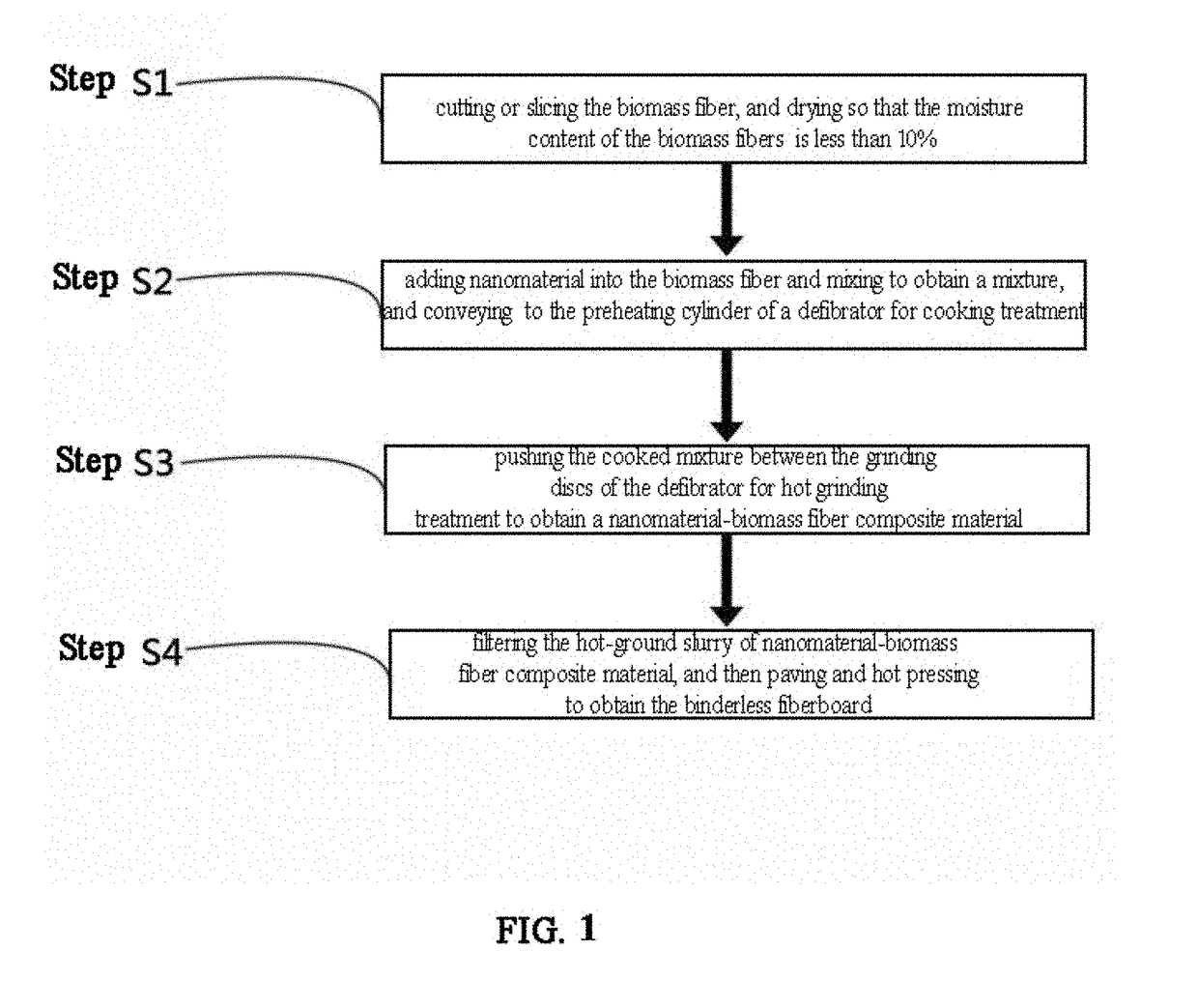
The present invention provides a method to make a nanomaterial-biomass fiber composite using a hot grinding process. This process not only causes physical changes in the wood fiber by splitting, deformation, and volume thinning, but also results in energy conversion and changes in the internal structure, physicochemical properties, and chemical reaction activity. This allows the wood fibers to be composited with previously prepared nano-particles without adding an adhesive in the hot pressing process. The invention has advantages of simple operation, low cost, low energy consumption, and suitability for industrialized production. The technical effects of the invention are provided in the form of a new method to create a high-quality fiber material with improved properties.

Problems solved by technology

There are many defects in the existing production of binderless fiberboards such as low bonding strength, high density, high brittleness, and easy water absorption.
However, the size of the fiber in the existing fiberboards with nano-particles added is relatively large, and the specific surface area of the fiber is so small that the internal fiber bonding is not closely enough, resulting in problems such as lower strength and larger thickness swelling rate of water absorption.
In addition, as disclosed in CN 104262982 A and CN 101745967 A, it is necessary to add additional auxiliaries and adhesives into the fiberboards with nano-particles added to achieve sufficient strength, which not only makes the preparation process complicated, but also causes the problem of formaldehyde emission from the products.

Method used


Image

  • Nanomaterial-biomass fiber composite and preparation method thereof
  • Nanomaterial-biomass fiber composite and preparation method thereof
  • Nanomaterial-biomass fiber composite and preparation method thereof

Examples


example 1

[0054]1. Cutting or slicing the biomass fiber, and then drying it to the extent that the moisture content of the biomass fiber is less than 10%, wherein the biomass fiber is wood;

[0055]2. adding nanomaterial into the biomass fiber and mixing them to obtain a mixture, and conveying the mixture to the preheating cylinder of a defibrator for cooking treatment, wherein the cooking temperature in the preheating cylinder is 100° C., the steam pressure is 0.01 MPa and the cooking time is 1 min; the nanomaterial is nano-TiO2, and the nanomaterial accounts for 0.01% of the absolute dry weight of the biomass fiber; and wherein the pH value of the cooked mixture is adjusted to 1 using H3PO4 aqueous solution before carrying out the hot grinding treatment;

[0056]3. pushing the cooked mixture between the grinding discs of the defibrator for hot grinding treatment, wherein the rotating speed for the hot grinding is 2880 rpm, and the time for the hot grinding treatment is 6 h; and

[0057]4. filtering ...

example 2

[0058]1. Cutting or slicing the biomass fiber, and then drying it to the extent that the moisture content of the biomass fiber is less than 10%, wherein the biomass fiber is bamboo;

[0059]2. conveying the nanomaterial to the discharge valve of the defibrator via a pipe and injecting it into the discharge valve via a nozzle so as to be mixed with the biomass fiber to obtain a mixture, and conveying the mixture to the preheating cylinder of the defibrator for cooking treatment, wherein the cooking temperature in the preheating cylinder is 110° C., the steam pressure is 0.02 MPa and the cooking time is 2 min; the nanomaterial is nano-ZnO, and the nanomaterial accounts for 0.02% of the absolute dry weight of the biomass fiber; and wherein the pH value of the cooked mixture is adjusted to 2 using HC1 aqueous solution before carrying out the hot grinding treatment;

[0060]3. pushing the cooked mixture between the grinding discs of the defibrator for hot grinding treatment, wherein the rotati...

example 3

[0062]1. Cutting or slicing the biomass fiber, and then drying it to the extent that the moisture content of the biomass fiber is less than 10%, wherein the biomass fiber is wood and its processing residues;

[0063]2. conveying the nanomaterial onto a wood chip at the feed inlet of the grinding chamber of the defibrator via a delivery pump, conveying it into the continuous discharge valve of the grinding chamber of the defibrator via a gear pump to be mixed with the biomass fiber to obtain a mixture, and conveying the mixture to the preheating cylinder of the defibrator for cooking treatment, wherein the cooking temperature in the preheating cylinder is 120° C., the steam pressure is 0.05 MPa and the cooking time is 4 min; the nanomaterial is nano-Ag, and the nanomaterial accounts for 0.04% of the absolute dry weight of the biomass fiber; and wherein the pH value of the cooked mixture is adjusted to 3 using H2SO4 aqueous solution before carrying out the hot grinding treatment;

[0064]3....


PUM

PropertyMeasurementUnit
Temperatureaaaaaaaaaa
Fractionaaaaaaaaaa

Abstract

A nanomaterial-biomass fiber composite and preparation method thereof. The biomass fibers are cut or sliced, and then dried. The dried biomass fibers are mixed with a nanomaterial and conveyed to the preheating cylinder of a defibrator for cooking treatment. The cooked mixture is pushed between the grinding discs of the defibrator for hot grinding treatment. The resulting material is then hot pressed to obtain the nanomaterial-biomass fiber composite material. The preparation method benefits from simple operation, low cost, low energy consumption, suitability for industrialized production, and wide application prospect in the field of production of binderless fiberboard.

Description

RELATED APPLICATIONS[0001]This application is a continuation-in-part application of the international application PCT / CN2017 / 105498 filed Oct. 10, 2017, which claims the benefit of the Chinese patent application CN201611047209.9 filed Nov. 23, 2016, each of which is incorporated herein by reference in its entirety.FIELD OF THE INVENTION[0002]The invention relates to the technical field of composite materials, in particular to a nanomaterial-biomass fiber composite and a preparation method thereof.BACKGROUND OF THE INVENTION[0003]Nanomaterials refer to materials that have at least one dimension in the three-dimensional space being in the nanoscale range (1-100 nm) or consist of them as basic units. Once the material's dimension enters the nanometer scale, the performance thereof has undergone a leap from quantitative change to qualitative change, resulting in new phenomena such as quantum size effect, small size effect, surface effect, and macroscopic quantum tunneling effect, and it...

Claims


Application Information

Patent Timeline
IPC IPC(8): C08K3/22C08K3/08C08K3/36C08L97/02C08K3/04
CPCC08K3/08C08K2003/2262C08L2205/16C08K3/36C08L97/02C08K3/042C08K3/046C08K3/041C08K2003/2241C08K2003/2296C08K2003/0806C08K2003/2275C08K2003/265C08K2003/2227C08K2003/2224C08K2003/2213C08K3/22C08J3/203C08K3/04C08K3/26C08J2401/02C08J2397/02C08K2201/011C08L1/02C08K7/06C08K7/24C08J3/2053
Inventor JIN, CHUNDELI, JIANSUN, QINGFENG
Owner ZHEJIANG FORESTRY UNIVERSITY
Learn More