
Method of bonding a laser activated remote phosphor assembly, method of manufacture and a laser activated remote phosphor assembly

a laser activated remote phosphor and assembly technology, applied in the direction of vacuum evaporation coating, semiconductor devices, coatings, etc., can solve the problems of inherently difficult maintenance and control, glass may spall off upon cooling, and production shut down, so as to improve production quality and production time

Active Publication Date: 2018-09-13
OSRAM GMBH
View PDF0 Cites 3 Cited by
  • Summary
  • Abstract
  • Description
  • Claims
  • Application Information

AI Technical Summary

Benefits of technology

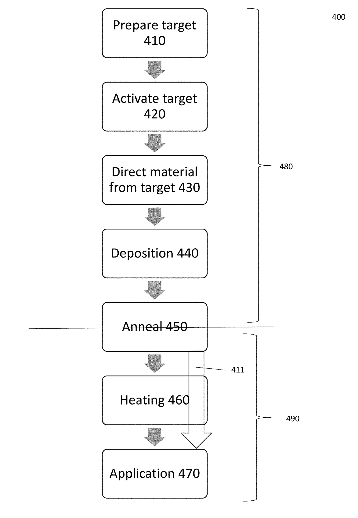
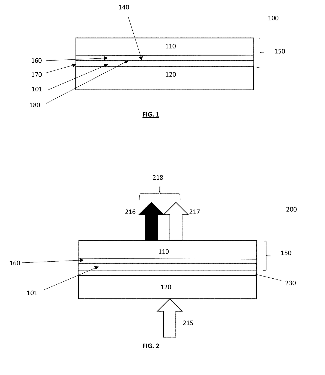
The disclosed method improves the production of laser-activated remote phosphor assemblies by enhancing the optical and thermal interface between wavelength converters and LED or dichroic materials through the use of thin film deposition of Te—Zn—Al—Na-Oxide glass compositions. This method allows for a high speed and high quality manufacturing process, resulting in improved quality of the bonding film and a uniform bond thickness that is optimal for better heat dissipation. The use of thin film vacuum technology is advantageous for obtaining a high quality optical interface, e.g. transparency. The thin film bonding method also eliminates contamination on the glass and reduces or eliminates bubbles in the bonded glass. Annealing the wavelength converters with the deposited bonding film may compensate for oxygen deficiencies in the wavelength converters. Overall, the method improves production quality and time of laser-activated remote phosphor assemblies.

Problems solved by technology

With the large difference in CTE between the glass and the material it is bonded to, the glass may spall off upon cooling.
This requires the glass dosing process, which is inherently difficult to maintain and control, to be an integral part of the assembly.
Any difficulty with dosing requires a shut-down of production.
For the liquid dosing process, control over bubbles in the glass fiber dosing process, weight control, contamination and special registering (correct location for glass) are inherently difficult.
It should be noted that the Te—Ze—Al—Na-Oxide glass is very susceptible to reduction, resulting in dark glass and bubbles when contaminated with organic matter.
Such process, however, along with being slow, could give non-uniform thickness within the bonding area if not optimized.

Method used


Image

  • Method of bonding a laser activated remote phosphor assembly, method of manufacture and a laser activated remote phosphor assembly
  • Method of bonding a laser activated remote phosphor assembly, method of manufacture and a laser activated remote phosphor assembly
  • Method of bonding a laser activated remote phosphor assembly, method of manufacture and a laser activated remote phosphor assembly

Examples


Embodiment Construction

[0042]The following detailed description refers to the accompanying drawings that show, by way of illustration, specific details and embodiments in which the invention may be practiced.

[0043]The word “exemplary” is used herein to mean “serving as an example, instance, or illustration”. Any embodiment or design described herein as “exemplary” is not necessarily to be construed as preferred or advantageous over other embodiments or designs.

[0044]The word “plural” and “multiple” are used herein to expressly refer to a quantity greater than one. Accordingly, any phrases explicitly invoking the aforementioned words (e.g. “a plurality of [objects]”, “multiple [objects]”) referring to a quantity of objects is intended to expressly refer more than one of the said objects. The terms “group”, “set”, “collection”, “series”, “sequence”, “grouping”, “selection”, etc., are used herein to mean a quantity equal to or greater than one, i.e. one or more. Accordingly, the phrases “a group of [objects]...


PUM

PropertyMeasurementUnit
Temperatureaaaaaaaaaa
Thicknessaaaaaaaaaa
Mechanical propertiesaaaaaaaaaa

Abstract

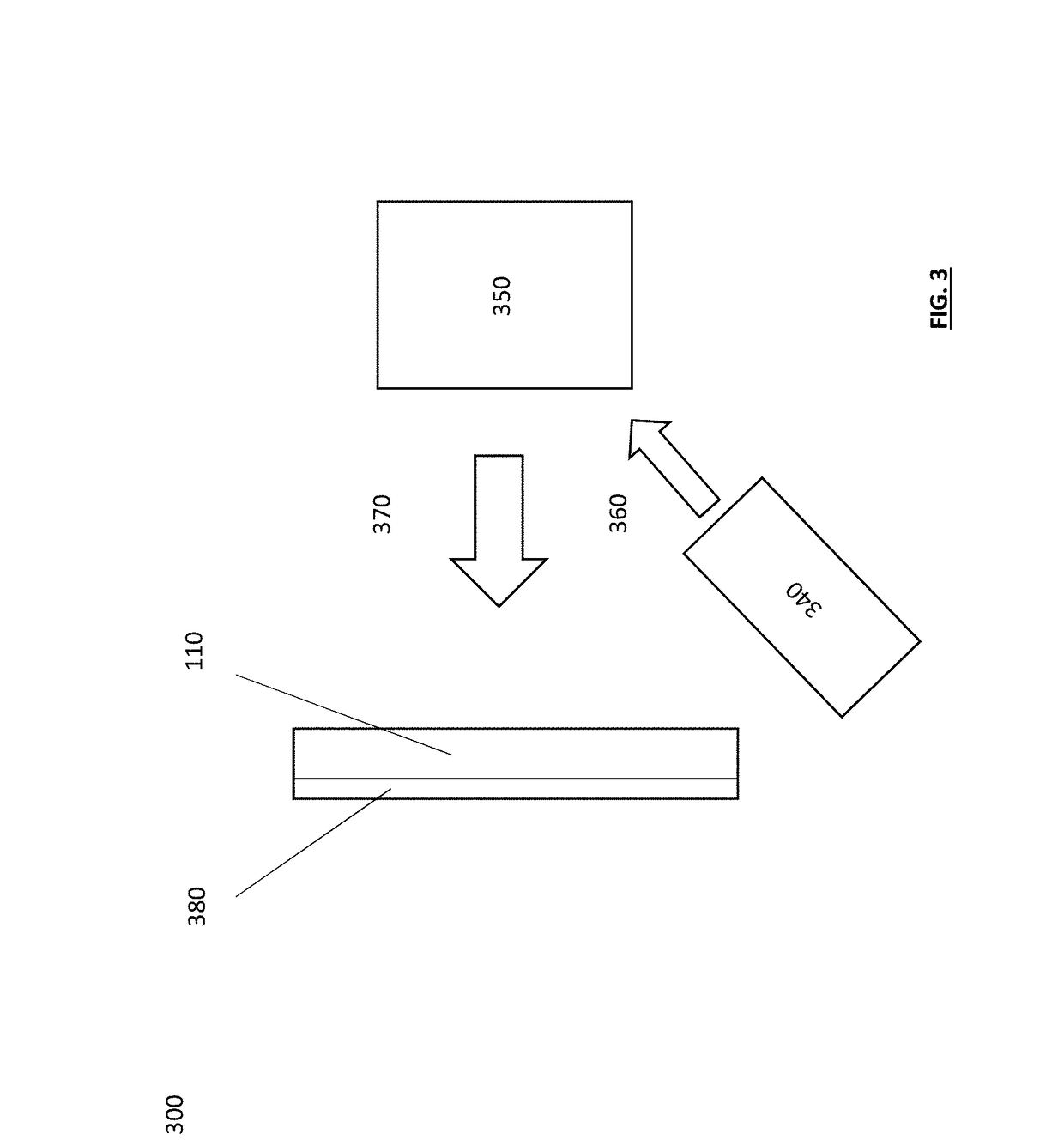
A method for producing a laser activated remote phosphor (LARP) sub-assembly, which may comprise: preparing a target composed of a material; activating the target such that the material is released from the target; directing the material released from the target in the direction of a wavelength converter and depositing the material released from the target onto a major surface of the wavelength converter creating a bonding film.

Description

TECHNICAL FIELD[0001]Various embodiments relate generally to a method of bonding a laser activated remote phosphor assembly, a method of manufacturing laser activated remote phosphor assemblies, and a laser activated remote phosphor assembly.BACKGROUND[0002]In current Laser Activated Remote Phosphor (LARP) applications, glass is deposited on a ceramic converter or a dichroic coated substrate by liquid glass dosing. Alternatively, a microgram sized fragment may be cut from a thin glass fiber and heated until the fiber melts. In both processes, the glass must remain melted from the time of deposition through final assembly, due to the large difference in the coefficient of thermal expansion (CTE) between the glass versus the dichroic coated substrate and the ceramic converter. With the large difference in CTE between the glass and the material it is bonded to, the glass may spall off upon cooling. This requires the glass dosing process, which is inherently difficult to maintain and co...

Claims


Application Information

Patent Timeline
IPC IPC(8): C23C14/08H01L33/50C23C14/28
CPCC23C14/088H01L2933/0041C23C14/28H01L33/505C23C14/08C23C14/5806H01L33/507
Inventor KUNDALIYA, DARSHANJOHNSTON, DAVID W.AVALLON, JAMES A.LENEF, ALAN L.
Owner OSRAM GMBH
Learn More