Gas control system, deposition apparatus including gas control system, and program and gas control method used for gas control system

a control system and control system technology, applied in the direction of process and machine control, instruments, transportation and packaging, etc., can solve the problems of difficult control of the total amount of material gas to be led out of the tank, occurrence of overshoot greatly exceeding the target concentration, and inability to reproduce the change in the concentration of material gas

Active Publication Date: 2018-09-13
HORIBA STEC CO LTD
View PDF8 Cites 11 Cited by
  • Summary
  • Abstract
  • Description
  • Claims
  • Application Information

AI Technical Summary

Benefits of technology

[0024]According to the present invention configured as described above, by preventing the material gas of high concentration produced in the tank by vaporization of the material in advance from being led out at once just after operation, overshoot can be suppre

Problems solved by technology

These phenomena cause the problem of occurrence of overshoot greatly exceeding the target concentration.
This causes the problem that when the material gas whose concentration is varied by the multiple factors is led out of the tank at once in the initial stage where the carrier gas is

Method used


Image

  • Gas control system, deposition apparatus including gas control system, and program and gas control method used for gas control system
  • Gas control system, deposition apparatus including gas control system, and program and gas control method used for gas control system
  • Gas control system, deposition apparatus including gas control system, and program and gas control method used for gas control system

Examples


first embodiment

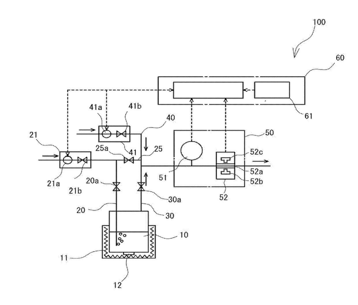
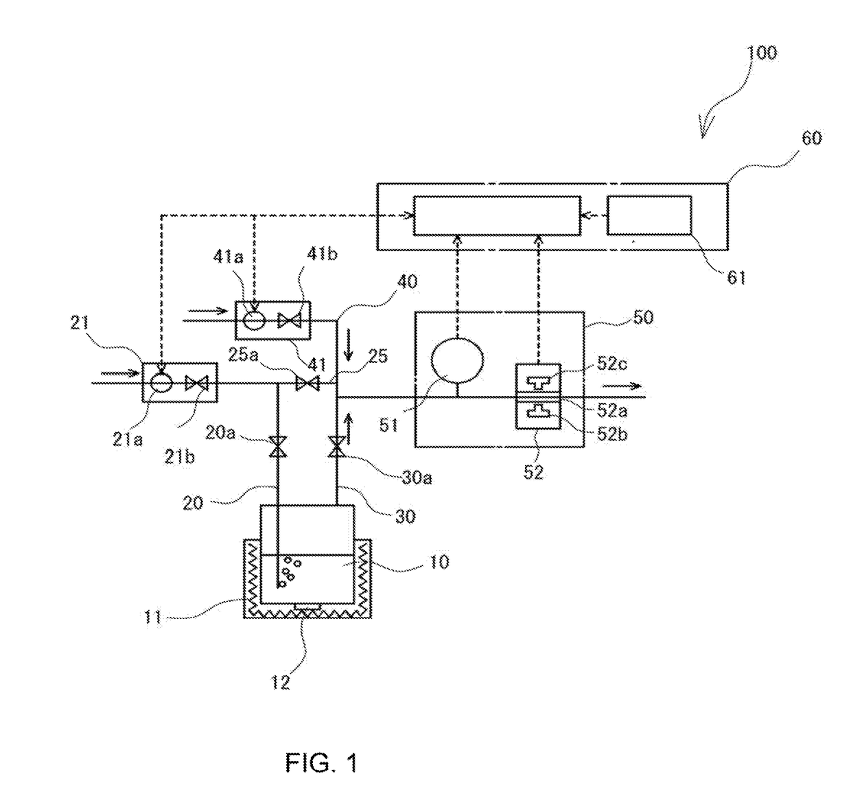
[0032]As illustrated in FIG. 1, a gas control system 100 according to the present embodiment includes: a tank 10 for containing a material; a carrier gas introduction path 20 for introducing carrier gas into a material space of the tank 10; a lead-out path 30 for leading out material gas and the carrier gas from a vapor phase space of the tank 10; and a diluent gas introduction path 40 for introducing diluent gas into the lead-out path 30. In addition, the carrier gas introduction path 20 and the lead-out path 30 are connected by a connecting path 25, and the carrier gas introduction path 20, the connecting path 25, and the lead-out path 30 are provided with valves 20a, 25a, and 30a, respectively. Further, the carrier gas introduction path 20 is installed with a carrier gas flow rate adjustment part 21 on the upstream side of the valve 20a, the diluent gas introduction path 40 is installed with a diluent gas flow rate adjustment part 41, and the lead-out path 30 is installed with a ...

second embodiment

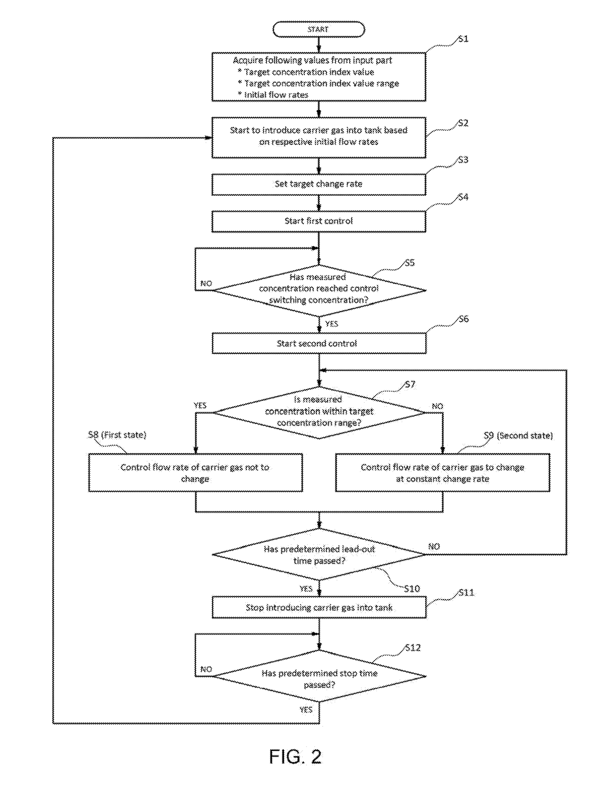
[0048]The present embodiment is a variation of the first control in the first embodiment (in particular, Step S3 in FIG. 2). That is, in the first control of the present embodiment, under different sets of conditions in which material conditions such as the nature and amount of the material, apparatus conditions such as the inside diameter of each pipe member and the capacity of the tank, external conditions such as temperature, and other such conditions are different, the initial change rate of the measured concentration is measured, and the initial change rate is preliminarily stored in an initial change rate data storage part as initial change rate data. Then, the control part sets the predetermined change rate with reference to the initial change rate data stored in the initial change rate data storage part.

third embodiment

[0049]The present embodiment is a variation of the second control in the first embodiment (Steps S6 to S11 in FIG. 2). That is, the second control of the present embodiment is PID control, and when the measured concentration comes into the first state, the proportional gain of the PID control is set to a predetermined value and thereby the PID control is performed so as to prevent the flow rate of the carrier gas from changing. On the other hand, when the measured concentration comes into the second state, the proportional gain of the PID control is set to a larger value than the predetermined value, and thereby the PID control is performed so as to bring the flow rate of the carrier gas close to the target concentration (see FIG. 5).

[0050]The present embodiment is adapted to, in the second control, when the measured concentration comes into the first state, set the proportional gain to the predetermined value, but may be adapted to set the predetermined value to zero and thereby pr...


PUM

PropertyMeasurementUnit
Flow rateaaaaaaaaaa
Concentrationaaaaaaaaaa

Abstract

The present invention makes it easy to control the amount of material gas led out of a tank. Accordingly, carrier gas is introduced into a tank containing a material and together with the carrier gas, from the tank, material gas produced by vaporization of the material is led out. A control part controls the flow rate of the carrier gas so that a concentration index value obtained by measuring mixed gas led out of the tank and indicating the concentration of the material gas in the mixed gas comes close to a predetermined target concentration index value. In addition, the control part controls the flow rate of the carrier gas to change at a predetermined change rate, and then controls the flow rate of the carrier gas on the basis of the deviation between the concentration index value and the target concentration index value.

Description

TECHNICAL FIELD[0001]The present invention relates to a gas control system, a deposition apparatus including the gas control system, and a program and gas control method used for the gas control system.BACKGROUND ART[0002]As a gas control system adapted to transport material gas used for deposition treatment in a semiconductor manufacturing process, as disclosed in Patent Literature 1, there is a gas control system adapted to introduce carrier gas into a tank containing a material, lead out material gas produced by vaporization of the material together with the carrier gas from the tank as mixed gas, measure the concentration of the material gas included in the mixed gas, and perform PID control of the flow rate of the carrier gas so as to bring the measured concentration close to a predetermined target concentration.[0003]However, in the conventional gas control system, the tank before operation is in a state of being filled with the material gas of high concentration produced by v...

Claims


Application Information

Patent Timeline
IPC IPC(8): C23C16/455G05D11/13
CPCC23C16/45523C23C16/45502C23C16/45512C23C16/45557G05D11/132C23C16/4482C23C16/52G05D11/138C23C16/45561H01L21/67017H01L21/67276H01L21/67253H01L21/0262Y10T137/2499Y10T137/2509
Inventor SAKAGUCHI, YUHEISHIMIZU, TORUMINAMI, MASAKAZUHAYASHI, DAISUKE
Owner HORIBA STEC CO LTD
Why Eureka
Try Eureka