Exhaust gas control apparatus of internal combustion engine

a control apparatus and exhaust gas technology, applied in mechanical equipment, machines/engines, charge feed systems, etc., can solve the problems of difficult to establish both an increase in the amount of egr gas and an the state of combustion is likely to deteriorate, and the likelihood of condensed water to be generated, etc., to suppress the increase in the boost pressure

Inactive Publication Date: 2018-09-20
TOYOTA JIDOSHA KK
View PDF0 Cites 7 Cited by
  • Summary
  • Abstract
  • Description
  • Claims
  • Application Information

AI Technical Summary

Benefits of technology

[0007]In the EGR device according to the aspect, the EGR valve is opened or closed in the cylinder. Thus, when the opening degree of the EGR valve is changed, the amount of EGR gas is immediately changed. That is, high responsiveness is achieved when the amount of EGR gas is controlled. Fresh air and EGR gas are mixed with each other in the cylinder. Thus, condensed water is unlikely to be generated. That is, fresh air receives heat from an intake passage while the fresh air is introduced into the cylinder, and the temperature of fresh air is comparatively increased. Thus, even when fresh air and EGR gas are mixed with each other in the cylinder, the temperature of mixed gas is unlikely to be decreased to or below the dew point. When EGR gas is supplied, the opening degree of an intake throttle valve or an exhaust throttle valve does not need to be decreased. Thus, pumping loss can be decreased. EGR gas is drawn from the downstream side of the turbine. Thus, even when EGR gas is supplied, the amount of exhaust gas passing through the turbine is not decreased. Accordingly, it is possible to supply EGR gas while a decrease in boost pressure is suppressed. EGR gas is drawn from the upstream side of the post-processing device. Thus, the amount of exhaust gas flowing into the post-processing device can be decreased by drawing EGR gas. Accordingly, exhaust gas can be suitably controlled in the post-processing device. The post-processing device can be exemplified by a catalyst or a particulate filter.
[0009]For example, the target temperature is the temperature in the cylinder at which the level of deterioration of emission falls within an allowable range. The temperature in the cylinder is the temperature of gas including fresh air and EGR gas in the cylinder. The temperature in the cylinder may be the temperature of gas at a predetermined crank angle at which fresh air and EGR gas are mixed with each other. When the temperature in the cylinder is low at the start or the like of the internal combustion engine, the state of combustion is likely to deteriorate. Increasing the temperature in the cylinder can suppress deterioration of the state of combustion. Therefore, the valve opening start timing of the EGR valve is adjusted such that the EGR valve starts to open in the exhaust stroke. Accordingly, the EGR valve is opened when the pressure in the cylinder is higher than the pressure in the EGR passage, and burned gas flows toward the EGR passage from the cylinder. In the intake stroke, the pressure in the cylinder is decreased when a piston moves down. Thus, by adjusting the valve closing completion timing of the EGR valve such that the EGR valve is fully closed in the intake stroke, burned gas that flows to the EGR passage from the cylinder in the exhaust stroke returns to the cylinder from the EGR passage in the intake stroke. When merely EGR gas that is introduced to the EGR passage from the exhaust passage is supplied, EGR gas loses heat to burned gas in the exhaust passage and the EGR passage, and the temperature of EGR gas is comparatively decreased. When burned gas that flows to the EGR passage from the cylinder is supplied as EGR gas, the amount of heat lost from EGR gas can be decreased, and EGR gas having a comparatively high temperature can be supplied into the cylinder. Thus, the temperature in the cylinder can be increased. When the temperature in the cylinder is higher than or equal to the target temperature, the amount of burned gas that flows to the EGR passage from the cylinder can be decreased by setting the valve opening start timing of the EGR valve to be in, for example, the intake stroke. Thus, an excessive increase in the temperature in the cylinder can be suppressed.
[0012]The non-return valve can restrict the amount of burned gas or fresh air that flows into the EGR passage from the cylinder. Accordingly, it is possible to suppress a decrease in the concentration of EGR gas due to fresh air that flows into the EGR passage from the cylinder. It is possible to suppress an excessive increase in the temperature of EGR gas due to high temperature burned gas that flows into the EGR passage from the cylinder.
[0014]When burned gas flows to the EGR passage from the cylinder in the exhaust stroke in order to increase the temperature of EGR gas, an amount of burned gas needed for the temperature adjustment needs to flow to the EGR passage from the cylinder. The temperature of EGR gas can be adjusted by disposing the non-return valve in a position where an amount of burned gas needed for the temperature adjustment flows to the EGR passage from the cylinder. That is, the temperature of EGR gas can be adjusted by disposing the non-return valve in a position where the capacity of the EGR passage from the EGR valve to the non-return valve is greater than or equal to the capacity corresponding to the amount of gas that flows to the EGR passage from the cylinder when the EGR valve is open in the exhaust stroke. By disposing the non-return valve, it is possible to suppress an amount of burned gas flowing to the EGR passage from the cylinder more than needed.
[0016]Accordingly, EGR gas passes through the non-return valve after the temperature of EGR gas is decreased by the EGR cooler, and an increase in the temperature of the non-return valve can be suppressed. Accordingly, deterioration of the non-return valve can be suppressed.
[0020]According to the aspect of the present disclosure, it is possible to suitably supply EGR gas while a decrease in boost pressure is suppressed.

Problems solved by technology

With the configuration in the related art, it is difficult to establish both of an increase in the amount of EGR gas and an increase in boost pressure.
Thus, condensed water is unlikely to be generated.
When the temperature in the cylinder is low at the start or the like of the internal combustion engine, the state of combustion is likely to deteriorate.

Method used


Image

  • Exhaust gas control apparatus of internal combustion engine
  • Exhaust gas control apparatus of internal combustion engine
  • Exhaust gas control apparatus of internal combustion engine

Examples


first embodiment

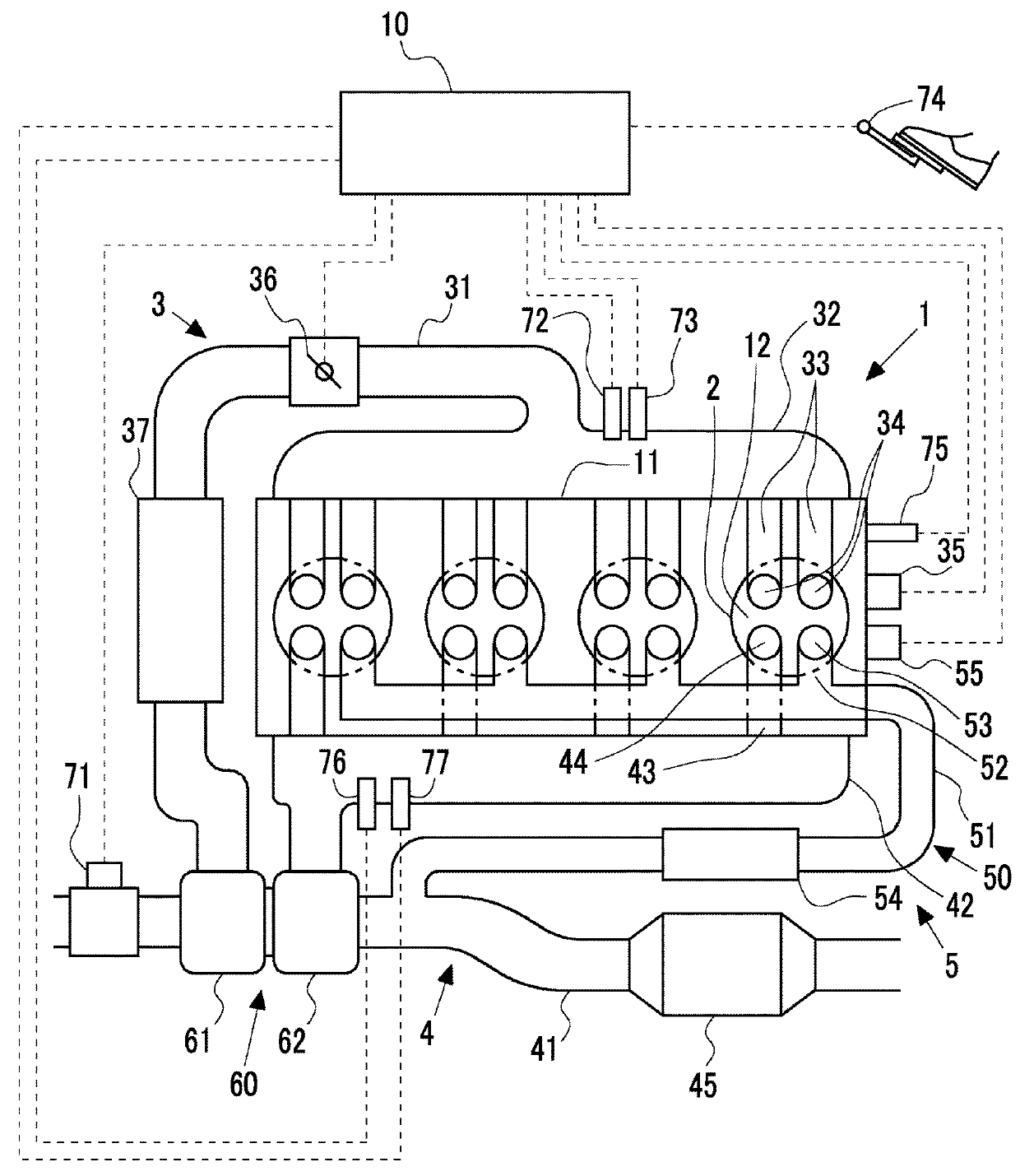
[0029]FIG. 1 is a diagram illustrating a schematic configuration of an internal combustion engine 1 according to a first embodiment. In the first embodiment, a part of constituents of the internal combustion engine 1 is not illustrated for simple illustration of the internal combustion engine 1. For example, the internal combustion engine 1 is mounted in a vehicle. The internal combustion engine 1 has four cylinders 2. The number of cylinders 2 of the internal combustion engine 1 is not limited to four.

[0030]An intake manifold 32 and an exhaust manifold 42 are connected to a cylinder head 11 of the internal combustion engine 1. The intake manifold 32 is a part of an intake pipe 31. The exhaust manifold 42 is a part of an exhaust pipe 41. An intake port 33 that is connected to each cylinder 2 from the intake manifold 32, and an exhaust port 43 that is connected to each cylinder 2 from the exhaust manifold 42 are formed in the cylinder head 11. An intake valve 34 is included in the cy...

second embodiment

[0062]In a second embodiment, the temperature of EGR gas is adjusted by adjusting the opening and closing timing of the EGR valve 53. Other devices and the like are the same as the first embodiment and thus, will not be described.

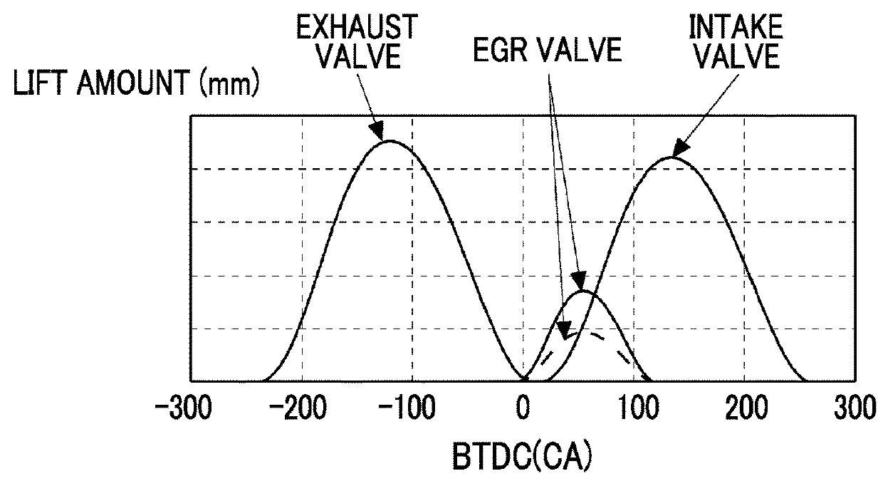
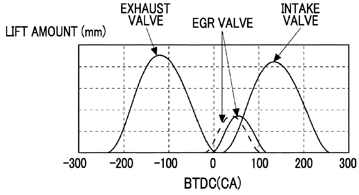
[0063]When the temperature in the cylinder 2 is low at the start or the like of the internal combustion engine 1, the state of combustion is likely to deteriorate. Increasing the temperature in the cylinder 2 can suppress deterioration of the state of combustion. Therefore, when the temperature in the cylinder 2 is lower than a target temperature, the ECU 10 according to the second embodiment adjusts the valve opening start timing of the

[0064]EGR valve 53 to set the temperature in the cylinder 2 to be higher than or equal to the target temperature.

[0065]FIG. 4 is a graph illustrating the relationship between the lift amount and the crank angle in each of the intake valve 34, the exhaust valve 44, and the EGR valve 53 when the temperature of EGR gas is adjus...

third embodiment

[0078]In a third embodiment, a non-return valve 56 is disposed in the middle of the EGR pipe 51. Other devices and the like are the same as the first embodiment or the second embodiment and thus, will not be described. FIG. 6 is a diagram illustrating a schematic configuration of the internal combustion engine 1 according to the third embodiment.

[0079]The non-return valve 56 is disposed in the EGR pipe 51 between the cylinder 2 and the EGR cooler 54. The non-return valve 56 is configured to allow EGR gas to pass to the cylinder 2 side from the exhaust pipe 41 side and not allow EGR gas to pass to the exhaust pipe 41 side from the cylinder 2 side.

[0080]While the non-return valve 56 can also be disposed in the EGR pipe 51 between the exhaust pipe 41 and the EGR cooler 54, disposing the non-return valve 56 in the EGR pipe 51 between the cylinder 2 and the EGR cooler 54 as illustrated in FIG. 6 can suppress high temperature EGR gas passing through the non-return valve 56. That is, when ...


PUM


Abstract

An exhaust gas control apparatus of an internal combustion engine includes a turbocharger including a turbine in an exhaust passage of the internal combustion engine, a post-processing device configured to control exhaust gas, the post-processing device being disposed in the exhaust passage downstream of the turbine, an EGR passage configured to connect the exhaust passage downstream of the turbine and upstream of the post-processing device with a cylinder of the internal combustion engine, and an EGR device including an EGR valve which is disposed in an end portion on the cylinder side of the EGR passage and opens or closes the EGR passage in the cylinder.

Description

INCORPORATION BY REFERENCE[0001]The disclosure of Japanese Patent Application No. 2017-048519 filed on Mar. 14, 2017 including the specification, drawings and abstract is incorporated herein by reference in its entirety.BACKGROUND1. Technical Field[0002]The present disclosure relates to an exhaust gas control apparatus of an internal combustion engine.2. Description of Related Art[0003]In a known technology (refer to, for example, Japanese Unexamined Patent Application Publication No. 2000-073875 (JP 2000-073875 A)), an exhaust gas recirculation (EGR) valve is disposed in a cylinder in order to directly recirculate exhaust gas in an exhaust manifold into the cylinder.SUMMARY[0004]When EGR gas is drawn from the upstream side of a turbine of a turbocharger, the amount of exhaust gas passing through the turbine is decreased by the amount of drawn EGR gas. Accordingly, when the amount of EGR gas is increased, the boost pressure may be decreased. With the configuration in the related art...

Claims


Application Information

Patent Timeline
Patent Type & Authority Applications(United States)
IPC IPC(8): F02M26/07F02M26/23F02M26/40F02M26/41
CPCF02M26/07F02M26/23F02M26/40F02M26/41F02M2026/004F02M26/44F02M26/39F02M26/38
Inventor AOYAGI, SHINSUKE
Owner TOYOTA JIDOSHA KK
Why Eureka
Try Eureka