Single point detection type microfluidic isoelectric focusing assay and chips using the same

Active Publication Date: 2018-09-27
MYONGJI UNIV IND & ACAD COOPERATION FOUND
View PDF3 Cites 0 Cited by
  • Summary
  • Abstract
  • Description
  • Claims
  • Application Information

AI Technical Summary

Benefits of technology

[0010]The single point detection type isoelectric focusing assay according to example embodiments may also downsize a detection instrument along with downsizing of the microfluidic chip and thus improve a protein assay system that depends on a conventional complex and expensive optical equipment.
[0011]As for the single point dete

Problems solved by technology

Since a currently developed and commercially available IEF system is mostly a fluorescence detection-based whole-column imaging system that uses a bulky equipment such as a fluorescence microscope and an expensive equipment such as a

Method used


Image

  • Single point detection type microfluidic isoelectric focusing assay and chips using the same
  • Single point detection type microfluidic isoelectric focusing assay and chips using the same
  • Single point detection type microfluidic isoelectric focusing assay and chips using the same

Examples


Example

Example 1

[0054]A numerical simulation about a microfluidic chip isoelectric focusing based on a contactless electrical conductivity measurement was performed by using a software of Simul 5. A 10 mm microfluidic channel, 0.625 mM carrier ampholyte (CA) within a range of pH 3 to 10, a 10 μM green fluorescent protein (GFP), a 70 mM H3PO4 anode solution, a 50 mM NaOH cathode solution, and a 200 V separation voltage were used as an simulation input. In addition, conductivity and concentration data were collected and analyzed as a function of time and position. The numerical simulation results are shown in FIG. 7. FIG. 7A shows an estimation result through a simulation of a protein concentration depending on a position of a microfluidic channel. Referring to FIG. 7A, two boundaries of protein move from both ends of the microfluidic channel toward a focusing point (an isoelectric point) (a dashed arrow). One hundred seconds later after the isoelectric focusing, two protein boundaries were ...

Example

Example 2

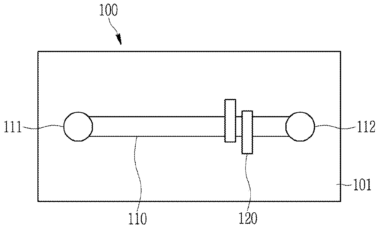
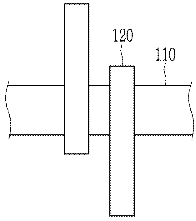
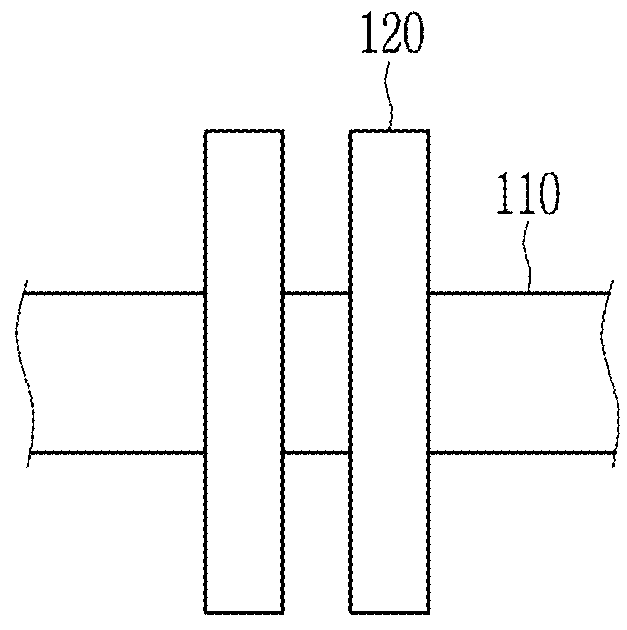
[0056]A cyclic olefin copolymer microfluidic chip having a 140 μm cover slip wherein a pair of electrodes is attached and a 18 mm straight microfluidic channel was used to analyze a protein through a microfluidic chip isoelectric focusing based on a contactless electrical conductivity measurement. The pair of electrodes has an electrode gap of 0.7 mm between themselves.

[0057]After cleaning the microfluidic chip, the internal surface of the microfluidic channel was coated with a 4% hydroxy ethyl cellulose (HEC). The HEC coating is to prevent non-specific attachment of a protein on the internal surface of the microfluidic channel and to minimize an electroosmotic flow.

[0058]A 25 μM green fluorescent protein (GFP) as a sample, a 2% carrier ampholyte (CA), and a 4% w / v HEC were loaded into the microfluidic channel. The loaded HEC functions as a dynamic coating and a separation matrix. In addition, 50 mM sodium hydroxide (NaOH) including 2% w / v HEC was added to the anode portion...


PUM


Abstract

The present invention relates to a single point detection type microfluidic chip isoelectric focusing. The single point detection type microfluidic chip isoelectric focusing uses a microfluidic chip including first and second electrode portions storing each electrode solution at both ends and a microfluidic channel between the first and second electrode portions and includes a focusing step of respectively connecting each electrode to the first electrode portion and the second electrode portion and applying an electric field thereto to separate a biomolecule to an isoelectric point, a mobilization step of moving the focused biomolecule toward a detection point by removing the electrode solution in the first electrode portion or the second electrode portion, and a detection step of the biomolecule moved toward the detection point.

Description

CROSS-REFERENCE TO RELATED APPLICATION[0001]This application claims priority to and the benefit of Korean Patent Application No. 10-2017-0038364 filed in the Korean Intellectual Property Office on Mar. 27, 2017, the entire contents of which are incorporated herein by reference.BACKGROUND OF THE INVENTION(a) Field of the Invention[0002]The present invention relates to an isoelectric focusing. More particularly, the present invention relates to a single point detection type microfluidic isoelectric focusing and a microfluidic chip for applying the same.(b) Description of the Related Art[0003]An isoelectric focusing (IEF) is an analytical technique of separating and detecting a protein, amino acid, DNA, RNA, a cell, a virus, and the like with a reference to an own inherent isoelectric point of a biomolecule. Particularly, the isoelectric focusing is generally used to analyze modification of the protein through an isoform, a post-translational modification, and a genetic recombination o...

Claims


Application Information

Patent Timeline
IPC IPC(8): G01N27/447
CPCG01N27/44704G01N27/44795G01N27/4473
Inventor KIM, DOHYUNSONG, JINAREGA, NEBIYU GETACHEW
Owner MYONGJI UNIV IND & ACAD COOPERATION FOUND
Why Eureka
Try Eureka